Author Archive
Spraying foam around the windows
One of the best home improvements I’ve made in a while, is one you’ll likely never see (unless you read this blog). And at about $10.00, it was also one of the cheapest projects I’ve done.
When the temperatures started to drop, I noticed that the second floor of my house was quite a bit colder than the first. So, I did what my mother had always done. I went out and bought window wrap, and applied it to all the windows in the house. You know the stuff. The plastic wrap, that shrinks with a hair dryer.

Yeah, that stuff.
After spending a day installing the stuff, I noticed it was still quite cold upstairs. As I investigated further, I found that I could still feel a draft near the windows. So I thought to my self “The air must be coming in around the window, not through it.”.
The next day I removed the casing from one of the windows, and found a puny bit of fiberglass batt insulation stuffed in around the window. I couldn’t believe that in a newer home, in the northern United States, this was the way they insulated around a window. I knew what had to be done, so I hopped in my truck and headed to Home Depot. Where I picked up two cans of Great Stuff™ Window & Door, for about $10.00.

If you’re going to do this, make sure you get the stuff designed for windows and door. The “regular” Great Stuff™ Gaps & Cracks may expand too much and/or too quickly, causing the window or door frame to bow out. If this happens, the door or window may not function properly. The window & door formula is created to expand with less force, so it will not bend the frame of a door or window.
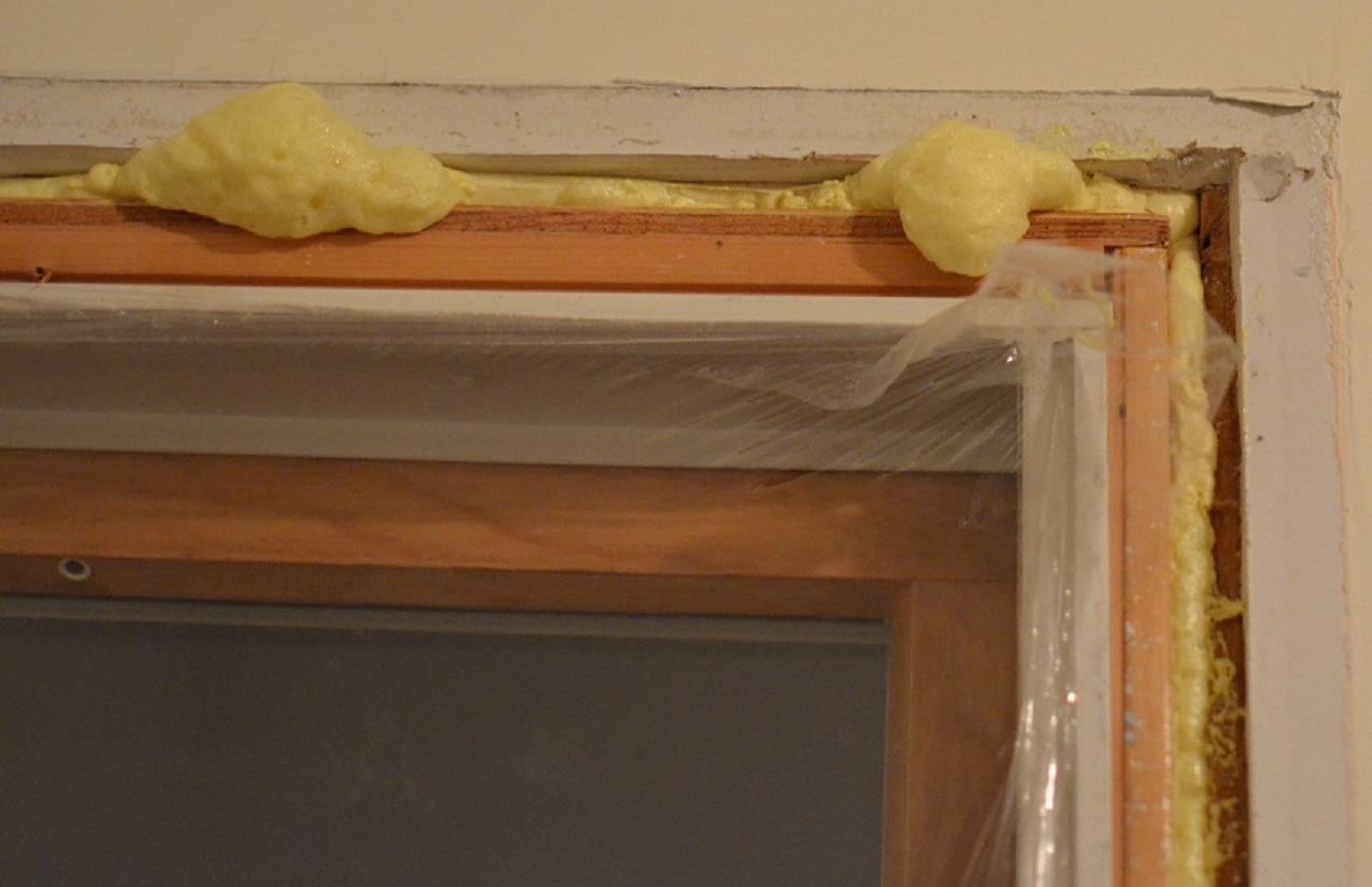
Installing the stuff is dead easy. Once you have the window trim removed, and the gap around the window frame revealed. You simply gently pull the trigger, and fill the gap about 50% of the way (that’s 50% of the depth, you want to fill the entire width). Run a smooth continuous bead in all the gaps, and sit back an watch it expand.

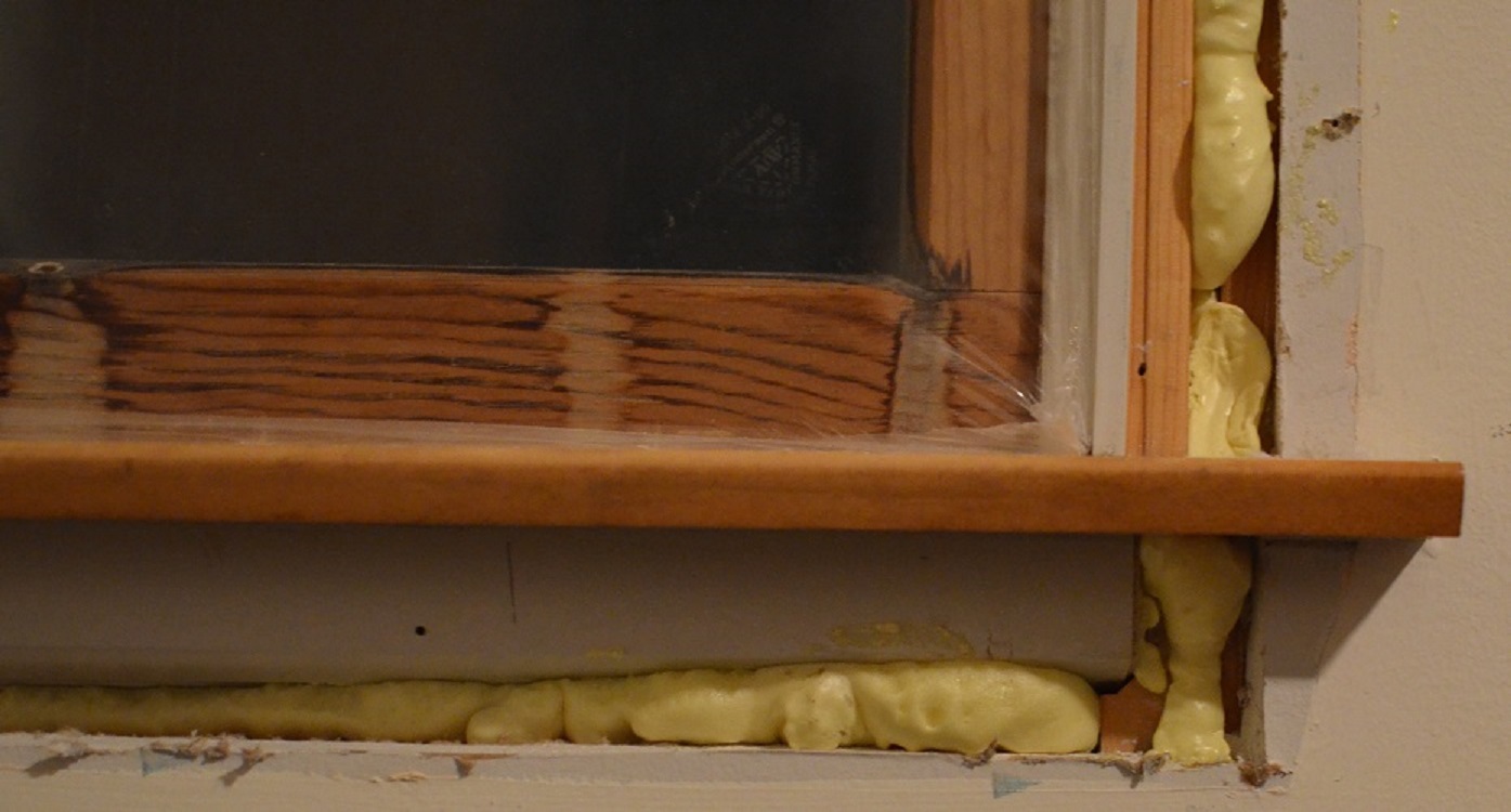
Don’t worry about being super neat, you can trim off anything that expands out of the crack later. Use a hack saw blade, or utility knife to trim off any excess, once the foam has cured (usually about 8 hours).
Once the foam has cured, and you’ve trimmed off any overflow. There’s nothing more to do except, install the casing, and celebrate a job well done.
I found that one 16 oz. can, was enough to do two standard sized windows. You’ll also want to be aware that once you start using a can, you have to use the whole can. If you don’t use all the product in the can, you cannot save the remainder for later. So before you start spraying, make sure the trim is removed from all the windows you plan to insulate.

Demystifying the mystifying GFCI
A commonly misunderstood electrical device, is the Ground-Fault Circuit Interrupter (GFCI). Whether posing as a circuit breaker, or a receptacle, the GFCI device is almost always misunderstood. To understand the GFCI, however, you have to know a bit (and I mean a really little bit) about transformers.
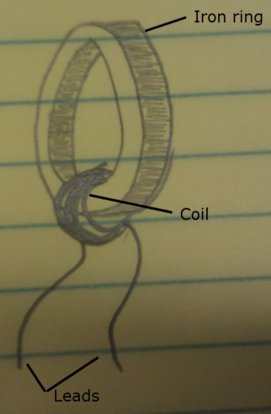
This is a transformer.
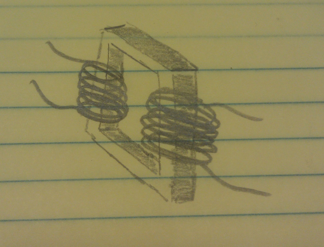
(Well, a crude representation of one anyway). It consists of an iron core, and a couple coils of wires.
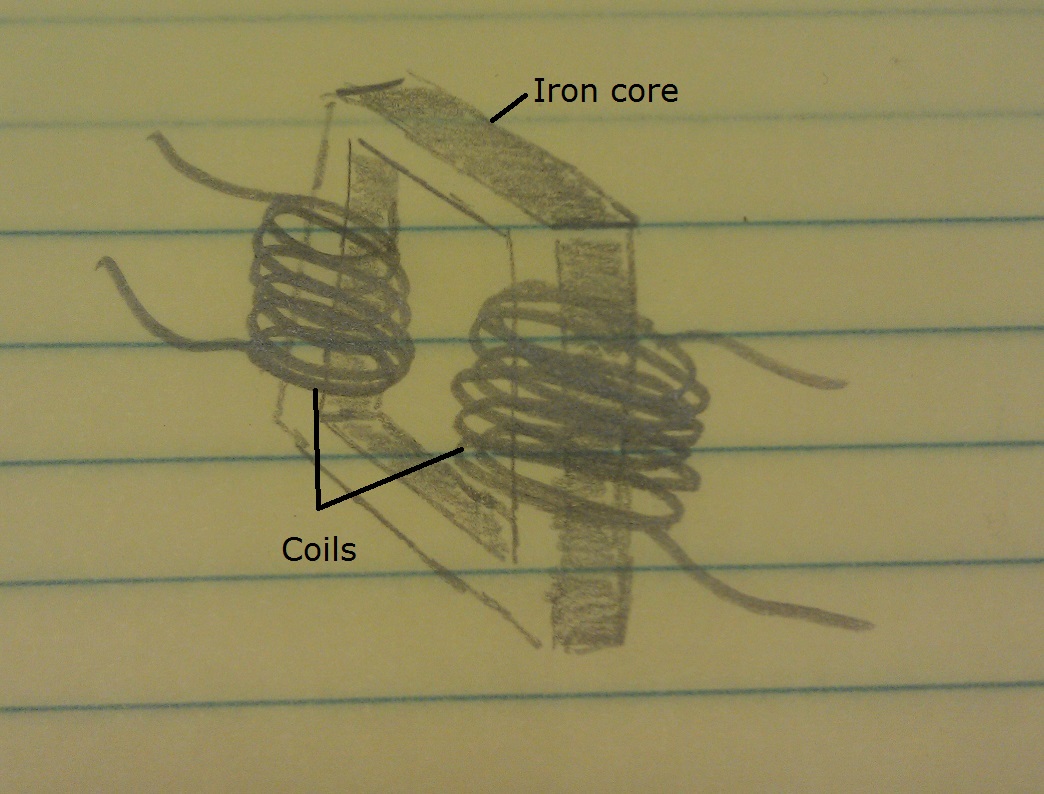
More specifically, it has a primary coil of wire, and a secondary coil of wire.

When you place a voltage on the primary coil, some magnetic magic happens in the core and a voltage is induced on the secondary coil.

And there you have the most basic crash course, on the most coarse basics of transformers. Which is all you need, to understand how GFCI devices work.
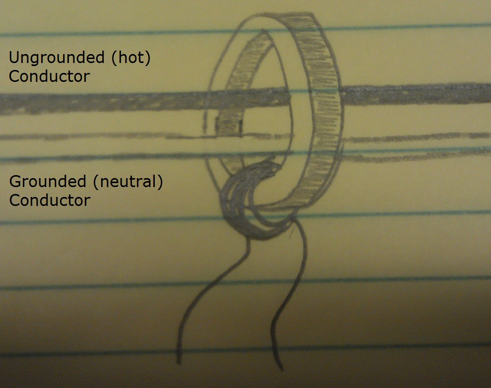
Inside a GFCI device, you’ll find what’s called a Current Transformer (CT). A crude representation of a CT, looks something like this.
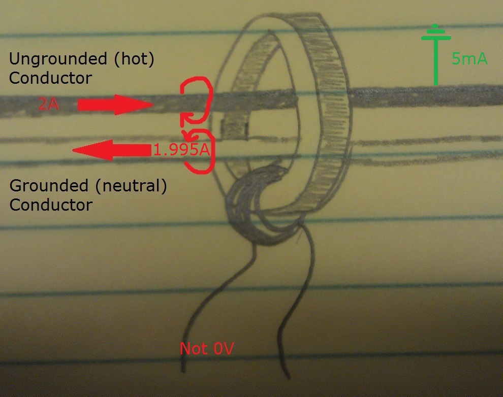
A CT works just like any other transformer. When a voltage is applied to the primary, a voltage is induced on the secondary. The only difference, is that the primary isn’t a coil, exactly. The primary is instead the ungrounded (hot), and grounded (neutral) conductors of an electrical circuit.
When current is drawn on the circuit, it flows down the ungrounded (hot) cunductor. Out to the consuming device, then returns back to the source on the grounded (neutral) conductor. Similarly, if we draw current from a GFCI device. It flows down through the ungrounded (hot) conductor, and through the CT core.
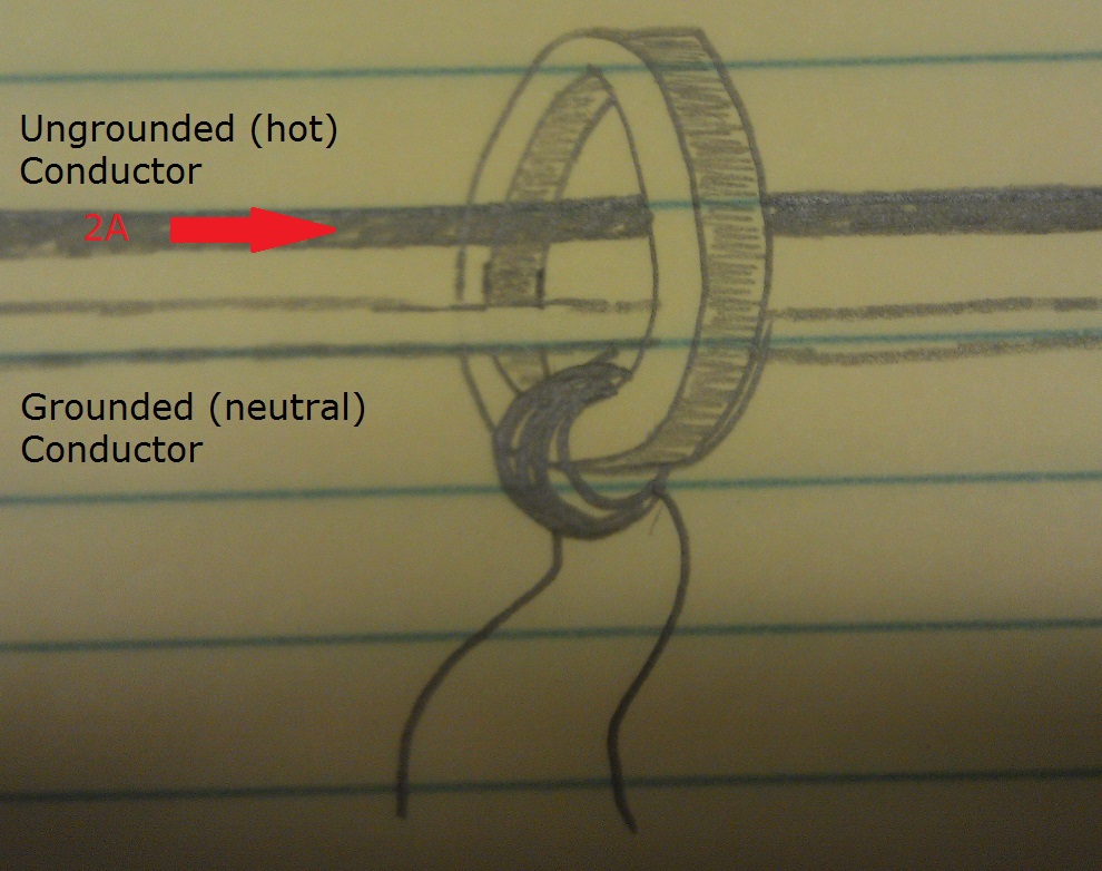
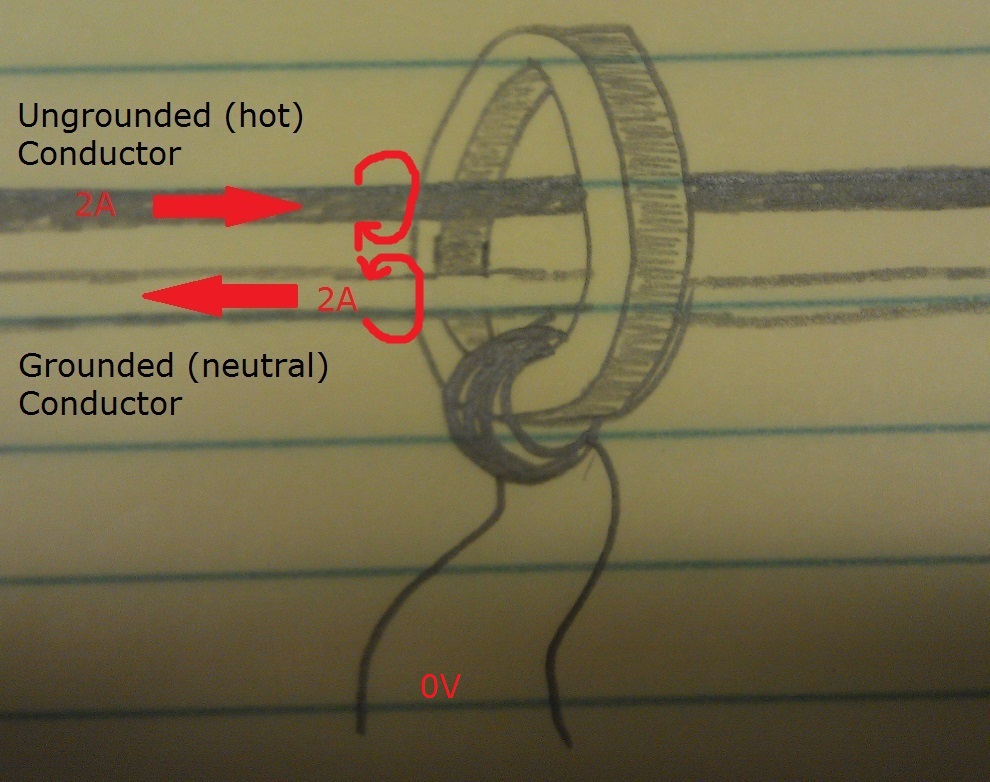
The current then flows back through the CT on the grounded (neutral) conductor, and back to the source.

According to the right hand rule. If you point the thumb of your right hand in the direction of current flow, and wrap your fingers around the conductor, your fingers point in the direction of the magnetic field produced by the flowing current. If this is done with the above diagram, we end up with magnetic field lines like this.

Because of the proximity, and opposite-ness of the fields. They cancel each other out, and no voltage is induced on the secondary coil of the CT.
In the case of a ground-fault, however, not all the current will flow back along the grounded (neutral) conductor. This creates an imbalance in the magnetic fields, which allows magnetic magic to occur in the transformer core, and a voltage is induced on the secondary of the CT. If the voltage on the CT is large enough, and lasts long enough, the GFCI device will open the circuit.
Next time you come across a GFCI device that continually trips, think about how it works and what it’s looking for. This might give you a better idea of what to look for, and where to start troubleshooting. And remember to always work safely, and cautiously whenever you’re working with electricity.
Replumbing an improper trap.
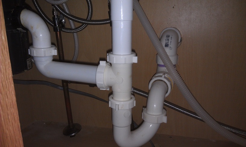
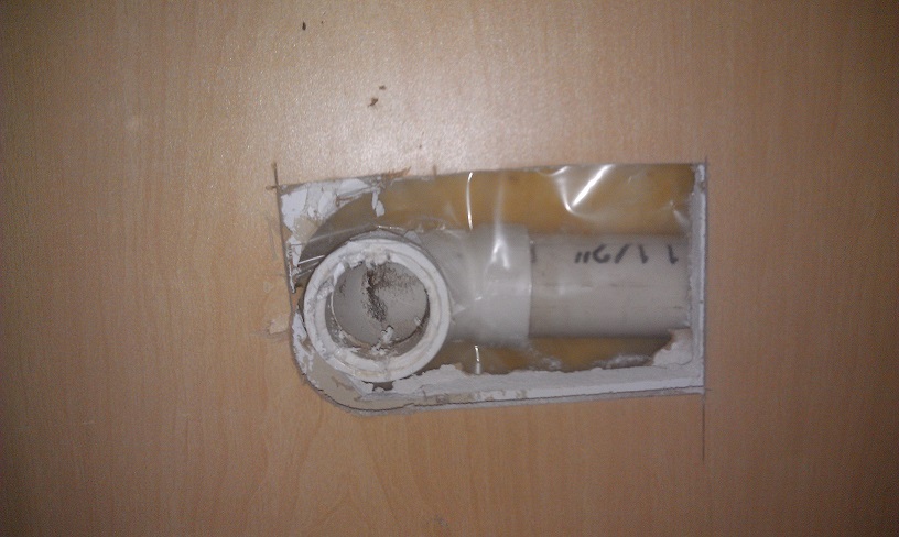
When I was inspecting the home that I recently purchased, I took a look under the kitchen sink and noticed this…
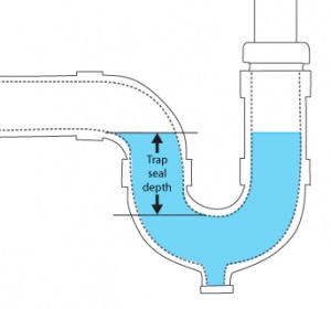
Typically, traps have a trap seal between 2 – 4 inches. This amount of water allows waste water and debris to flow down the drain, while still providing enough force to prevent sewer gases from pushing past. The problem you find with a deeper trap, is that the waste water; and in particular the debris, does not have enough force behind it to escape the trap. This leads to a nasty, dirty, stinkin’, slow flowing trap. Which leads to your wife saying “Dang, this sink stinks!”. If Google Nose BETA worked, I would have saved the smell from when the old trap was removed. Then you’d smell what I’m talking about.
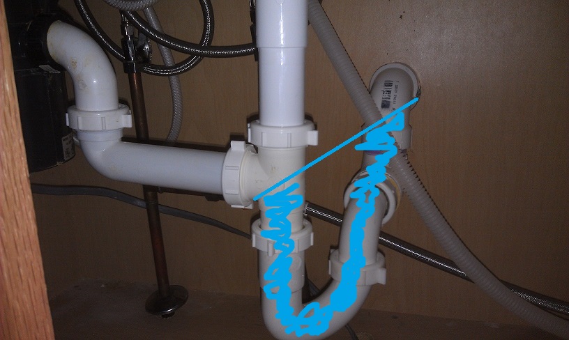
If you take a look back at the first image, you’ll see that the trap seal is simply too large. The entire pipe below the disposal drain line, all the way to the lower dip of the elbow coming out of the wall will be filled with water. Where in a normal situation, only the lower bend of the P-trap will be filled with water.
Usually this situation is fixed easily by purchasing the correct fittings, and connecting them in a way that allows proper drainage. In my case, however, some genius glued a downward facing elbow at the outlet connection. As soon as this elbow was glued in place, the fate of this trap was sealed. It would forever be WRONG!
To fix this problem, my only choice was to cut the offending elbow off. Once removed, new pipes could be connected, and a proper trap could be arranged. So I set about cutting the elbow off, as close to the back of the elbow as possible. The idea was to leave enough pipe behind the elbow, to allow me to attach new fittings. Unfortunately; as with most home improvement projects I ran in to problems and, this was not possible.

To leave the maximum amount of pipe, I used a hacksaw blade (removed from the hacksaw) to cut the pipe. If you attempt this, don’t forget to wear a good pair of leather gloves, or to wrap the ends of the blade with duct tape to make makeshift handles.
As it turned out the stub was just too short, so there was no way I was going to attach anything to the exposed pipe. My only option was to move back one more fitting, and cut the pipe beyond that. In this situation, this involved opening up the wall a bit. Fortunately I was working under a sink, in a cabinet, so a limited amount of damage was acceptable. I grabbed my trusty Milwaukee multi-tool, and cut a hole in the back of the cabinet and the drywall.
In a lot of instances this fitting will be a tee connecting the sink drain to a drain-waste-vent stack, which may require a bit more damage to the back of the cabinet and wall. In my situation, I was lucky it was a simple elbow.
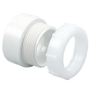
Using my hacksaw blade. I cut off the tee, glued on a new tee, glued on a short stub, and finally glued on a PVC DWV trap adapter.
Once that was done, it was a simple matter of installing the remaining bits of pipe.
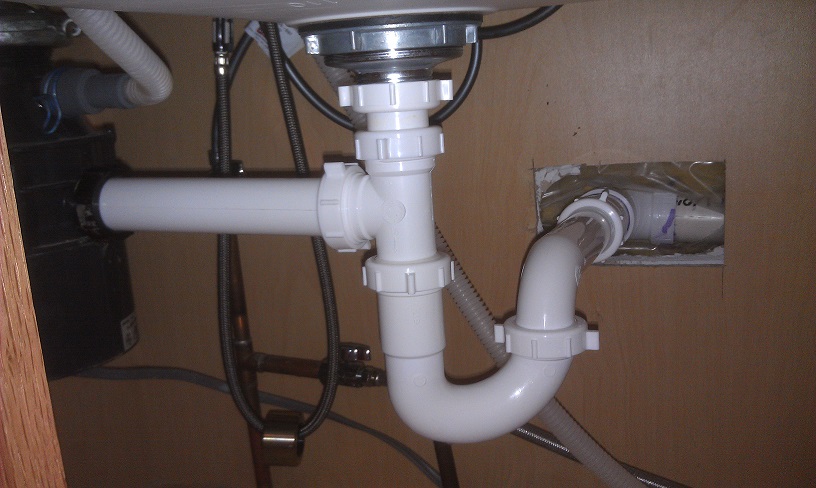
Now my trap is just the right depth, and the waste is flowing as it should.

Handling the pressure with expansion tanks
Is an expansion tank required?
Private, older public, and some other water distribution systems may not require an expansion tank to be installed. This is because these systems may be considered “open”, since they lack pressure regulators and/or backflow preventers. Plumbing code changes intended to prevent the contamination of the public water supplies, have made backflow prevention a requirement in most current new builds. While this may be a good change for the water supply, it can be a damaging change to your plumbing system.
IRC2009 P2902.3 Backflow protection. A means of protection against backflow shall be provided in accordance with Sections P2902.3.1 through P2902.3.6. Backflow prevention applications shall conform to Table P2902.3, except as specifically stated in Sections P2902.4 through P2902.5.5.
Before pressure reducing valves and backflow preventers were used, any excess pressure in your system could easily spread back into the water distribution system. This meant any thermal expansion of the water caused by your domestic hot water (DHW) system, could easily be dissipated back through the distribution system. Now that backflow prevention is required, your plumbing system has become a “closed” system, and a new way must be employed to prevent over pressurization.
This is where expansion tanks come in. Expansion tanks are used to absorb any excess pressure created due to thermal expansion, which prevents an over pressurization of the system. In any situation where water in a “closed system” is heated, an expansion tank is required.
IRC 2009 P2903.4 Thermal expansion control. A means for controlling increased pressure caused by thermal expansion shall be installed where required in accordance with Sections P2903.4.1 and P2903.4.2. P2903.4.1 Pressure-reducing valve. For water service system sizes up to and including 2 inches (51 mm), a device for controlling pressure shall be installed where, because of thermal expansion, the pressure on the downstream side of a pressure-reducing valve exceeds the pressure-reducing valve setting. P2903.4.2 Backflow prevention device or check valve. Where a backflow prevention device, check valve or other device is installed on a water supply system using storage water heating equipment such that thermal expansion causes an increase in pressure, a device for controlling pressure shall be installed.
Symptoms of an over pressurized system
High pressure in a plumbing system can damage any fixture connected to the system, including faucets, taps, toilets, washing machines, dish washers, water heaters, etc. It can also lead to leaks, running toilets, difficult to operate faucets and taps, and even burst pipes. A frequent symptom of an over pressurized system, is a sudden surge of water when a faucet is turned on. The surge will quickly dissipate, and won’t return even if you close and reopen the valve.
If the over pressurization is caused by thermal expansion, you may only notice symptoms occasionally and seemingly randomly. This is because the pressure in the system increases when the water heater is heating, and all fixtures are closed. The pressure diminishes when any fixture is opened, or as the water cools. The problem may only be observed when the system pressure is at its highest, which may only be on rare occasions.
What is an expansion tank?
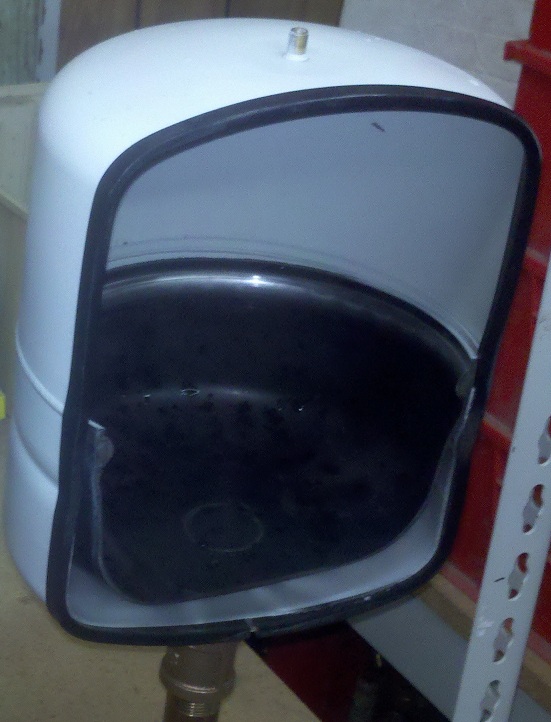
An expansion tank physically resembles a small propane tank.
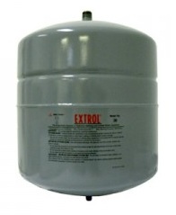
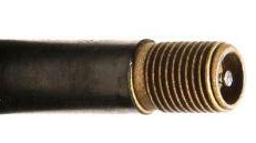
It’s usually installed fairly close to a water heater or boiler, and may be installed in almost any orientation. Internally, there will likely be a flexible (Butyl) diaphragm which divides the tank in two. On the “wet” side, you’ll notice a 3/4” NPTM connection which allows it to be connected to the plumbing system. The “dry” side, often features a Schrader valve which allows the pressure of the tank to be adjusted as needed.
Normally the tank will be completely filled with air, and the diaphragm will be pressing against the water inlet. As the water pressure increases, it compresses the lower pressure air in the tank, and the tank fills with water. When the system water pressure decreases, the air pressure forces the water out of the tank, and back into the pipes.
How do I install an expansion tank?
Expansion tanks are installed on the cold water supply of a domestic hot water tank, or boiler. The installation process is fairly easy, usually only requiring a tee fitting to be added to the water line.
Positioning
The first step in installing an expansion tank, is to decide where you want it. We already know that the tank must be installed between the cold water shut off, and the water heater inlet. So we know where it has to connect to the system, but we still have to decide where the tank itself will sit.
Up, Down, Left, or Right?
Most tanks can be installed in any orientation, though there are advantages to some positions. For example. If you install the tank vertically with the air side up, and the tanks bladder ever fails. The tank may continue to function (though at a reduced capacity), until the air escapes from the tank. Whereas, if the tank was installed with the air side down, and the bladder failed. The air would immediately move to the top of the tank, and the tank would fill completely with water.
Support
While most smaller tanks can be supported by the plumbing itself, it can be a good idea to support the tank by other means. Water weighs about 8.34 lbs/gallon, which means even a properly functioning tank can weigh quite a bit. Lets look at an example tank.
- Tank Capacity: 4.4 gallons.
- Maximum Accept Capacity: 2.5 gallons
- Tank Weight: 8 lbs
Maximum Properly Functioning Weight:
2.5 gallons * 8.35 lbs/gal. + 8 lbs = 28.875 lbs.
Maximum Failure Weight:
4.4 gallons * 8.35 lbs/gal. + 8 lbs = 44.74 lbs.
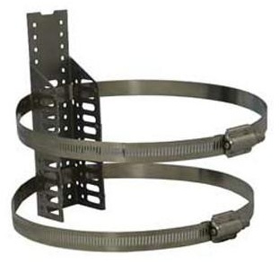
Even when the tank is in working order and fills to maximum capacity, you could end up with almost 29 lbs hanging from your pipes. Because of this, it may be a good idea to attach the tank to a nearby structural member. This can be easily accomplished, using straps and/or brackets designed for this purpose.
Installation
Now that we’ve decided where the tank will connect to the plumbing, and where the tank will spend the rest of its life. It’s time to start the actual installation.
Turn off the water
The first thing you’ll have to do is to figure out how to turn off the water heater/boiler, and then actually turn it off. Next you’ll have to locate the cold water supply shutoff valve, and turn the valve to the closed (off) position. Finally, turn on (open) the lowest hot water tap in the house. This will release any built up pressure, and prevent water from spraying out when you cut the pipe in the next step.
Mark and cut the pipe
Use the tee as a guide, and mark the pipe where you’ll be installing the tee. Cut the pipe at your marks, using a pipe cutter.

If you don’t have to cut the pipe, skip this step.
Install the tee
Solder, snap, or twist the tee into place. Then install any nipples or extension pipes required to reach the tanks final resting place. You’ll want to end the extension with a 3/4” NPTF fitting, so the expansion tank can be screwed into place.
At this point you may want to think about adding some extra fittings that will make required maintenance easier. A ball valve and spigot, will make isolating and draining the tank much more convenient. Installing a combination fitting like this Ball drain valve, can make this task much easier and clean looking (Make sure to check your local codes to insure this type of setup is allowed.).

Check the system pressure
 At this point you’ll want to close the faucet you opened, and open the shutoff valves (make sure you cap the extension pipe, or close the valve on the extension, or you’ll have water everywhere). Turn on all the hot water fixtures in the house until water flows normally (no sputtering), to insure the system is filled and at full pressure. Check for, and repair leaks.
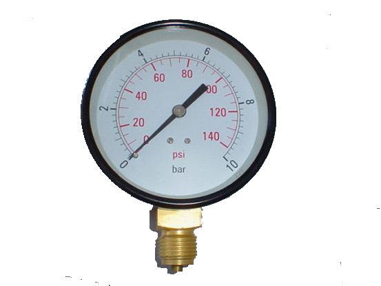
Attach a pressure gauge to any part of your plumbing system. Some gauges contain threads for a garden faucet, or you can attach one to the extension where the expansion tank will be installed. Once the gauge is attached, open the valve to get a reading on the gauge. Note the pressure. If the pressure is not within the normal range of 40 – 80 psi, you’ll have to take steps to correct it (which is not covered in this article).
Pre-pressurize the tank
Most expansion tanks come pressurized to 12 – 40 psi, but before you install the tank you have to match the system pressure. Start by removing the protective cover from the air valve on the tank. Use a tire gauge to check the pressure. Use a bicycle pump, or compressor, to fill the tank to match the system pressure you noted earlier.
Mount the tank
Attach the tank to the plumbing, and mount it using your straps and/or brackets. Turn everything on, and check for/repair any leaks. Stand back and revel in your success.
Maintenance
You can quickly verify the tank is working at any time, with a simple tap. When you tap on the air side of the tank, you should hear a hollow sounding dong. If you hear a solid sounding thud, the tank has failed, and is filled with water. In this case, the tank will have to be replaced.
Check the tank pressure
Once a year (see owners manual for schedule) or so, the air pressure in the tank should be checked. To do this, you’ll have to isolate the tank from the water systems pressure (Once again the extra valve and spigot come in handy). As before, you’ll have to shut off, open, close, or disconnect things until there is no pressure on the water side of the tank. Once you’ve accomplished that, use a tire gauge to check the air pressure. Add/remove air as needed. Repressurize the water system, and you’re good for another year.
Knowing when to say when
One of the most important skills a do it yourselfer can have, is knowing what you can do yourself and what you can’t. While doing work yourself can often save you a bit of money, doing things wrong can cost you more than you might think. Admitting to yourself that you can’t do something is often a very difficult and frustrating task, but realizing you shouldn’t have done something yourself can be much worse.
Trying new things is one of the best ways to learn what you can and cannot do, so you should never be afraid to try things. Learning a new skill or finding that you can do more than you thought, can be a great feeling. The best way to try and learn new things, is to do so under the supervision of a person who already knows how to do those things. Most community colleges; and some big box hardware stores, offer courses that can teach you how to do things yourself in a safe environment. Learning a new trade can be much easier in a risk free environment, where failure only means that you have to try again. Maybe you have a friend or family member who is knowledgeable in this field, and is willing to teach you what they know.
The worst place to learn a new trade is in the dark, crawling through mud, at 4:00 A.M., in a cramped space, with your family yelling at you because the water has been shut off for 12 hours. Learning in a situation like this only leads to mistakes, frustration, and failure, so you should make sure you’re comfortable with the work you’re about to do, and confident in your ability to do it, before you begin.
While almost any job around the house can be a do it yourself task, some jobs require more training and a good understanding of the underlying system to be completed successfully.
Plumbing
While some plumbing jobs require only a small amount of skill (changing a faucet, unclogging a drain, fixing a leaky toilet, etc.), others require training, planning, skill, and experience. Some aspects of plumbing can be done by almost anybody, but may only be done well by an experienced tradesman. Soldering joints, for example, is a task that can be done by almost anybody, but only a true master can do it artfully.
Plumbing is one of those things where you might think “You just connect pipes, how hard can that be”, until you end up with a stream of never ending water flooding your basement.

Plumbing is one of the vital systems in your home, which goes unnoticed most of the time but can cause a lot of grief when it’s not working. You might think “I’ll just shut off the water, make this connection, and I’ll be done”. Then you find yourself 6 hours later, standing in a puddle, dripping wet, with your legs crossed trying not to soil your pants.
The best way to learn how to plumb, is to do it where there are little to no consequences. Soldering scrap pieces of pipe in the garage, is a great safe way to learn to solder. Practice these skills before you start working on such a vital system in your home. Spend some time figuring out exactly what you’ll have to do to complete the job, then make a good plan and stick to it. Do as much work as you can before you shut off the water supply, this will minimize the systems down time (and help you avoid soiling your pants).
Electrical
This field of work requires at least a slight understanding of how electricity behaves in order to be able to complete simple tasks such as replacing receptacles, changing light fixtures, replacing switches, and other small activities. However, most jobs require a fairly good grasp of electrical concepts, electrical codes and best practices, and some form of training. This is not a trade for novice do it yourselfers, and in most cases work should be completed by; or at least inspected by, a capable, licensed Electrician.
Becoming capable of doing electrical work yourself will require fairly major investments in both learning and tools, so be prepared to spend a lot of time and money if you are thinking of tackling these types of jobs.
The basics of electrical work can be learned relatively quickly, but the knowledge required to complete tasks grows exponentially as you become more involved with larger sections of the electrical system. Learning to replace a light fixture can be quick and easy. Learning to install and troubleshoot whole circuits, can take a long time and require a lot of specialized tools.
Electrical work can be very dangerous, and can cause personal injury, death, and/or property damage if done incorrectly. This is why training, and a good understanding of the basic concepts is so important. Do it yourselfers should have a fairly good understanding of how electrical systems work, and what tools are required, before deciding if they should complete any electrical work themselves.
HVAC
Heating ventilation and air conditioning jobs often require both plumbing and electrical skills, and apart from minor jobs (replacing a thermostat, changing filters, etc.) they should not be preformed by unqualified persons. HVAC systems can cause personal injury, death, and property damage, if not installed and maintained properly. It requires an in-depth knowledge of the systems involved to safely complete HVAC jobs, which often means this type of work should be avoided by a do it yourselfer.
This type of work will require training, specialized tools, and a solid understanding of electricity, plumbing, fluid dynamics, thermal dynamics, high and low pressure systems, and electronics.
While there are other dangerous systems and jobs throughout the house, electrical, plumbing, and HVAC can be the most hazardous for do it yourselfers. With the high prices that professionals in this field charge, it’s often tempting to try and avoid these expenses. In most cases, however, it’s safer and more cost effective (in the long run) to simply allow a professional to complete this type of work. Saving a few dollars, is never worth risking your families safety and well being.
Tool Review: Ideal Lil’ Ripper Stripper™
I recently picked up the Lil’ Ripper Stripper™ from Ideal Industries, at Home Depot for about $5.00.
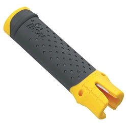
Not that I needed a new tool, especially another wire stripper; but for $5.00, how could I resist?
Really, I was just interested to see how useful it actually was. I’m almost always skeptical of multi-tools, since they aim to replace tools designed specifically for a single task. The Lil’ Ripper Stripper is no exception, so it really has to preform well to replace tools in my tool pouch.
Features:
- Rips Romex® wire outer jacket cleanly and quickly.
- Clips outer sheathing to remove excess Romex® wire jacket.
- Strips inner conduit wires.
- Looping holes loop wire for screw-on connections.
- Twist-Assist™ tightens most popular sizes of winged twist-on wire connectors.
- Injection molded elastomer grip provides a comfortable, slip resistant grip.
- Strip length measuring scale allows for quick and easy measurements.
- Conveniently fits in your pocket.
Since Ideal gave me a good feature list, lets tackle each one individually.
Ripping Romex® (NM wire)
The Lil’ Ripper Stripper, makes ripping non-metallic cable sheath simple and fast. If you look in one end of the tool, you’ll notice a small metal hook.

To rip the cable, simply place the hook under the cable sheathing, then slide the tool along the cable. The Lil’ Ripper Stripper definitely earns this part of its name, this thing rips cable like a champ. It slices through the sheath clean, fast, and without any concern of nicking the conductors. Because of its shape and size, you can even easily rip the sheath from cables already installed in boxes.
Removing excess sheathing
To remove the excess sheathing, you slide the sheathing into the large notch, at the end of the tool, and pull.
This feature seemed like an afterthought, or maybe the cutting blade was relocated to accommodate another feature. Either way, it’s not great at this. The cutting blade is set back a bit too far, which makes getting the excess sheath deep enough to cut it a challenge. Even the guy in the demo video had trouble with this feature, so it doesn’t seem to be user error on my part.
Stripping conductors
To strip the conductors, you simply slide the wire into the V notch at the end of the tool, give it a couple twists, then pull the insulation off.

It works relatively well, though it can easily nick the conductors if the wire is inserted too forcefully. You’ll also notice a measuring scale on the face of the tool, which helps you determine how much insulation to remove.

Terminal loops
To create terminal loops in the wire, you insert the wire into one of two holes on the side of the tool, then give it a quarter turn.

This is a nice feature, and works very well.
Twist-Assist™
To twist on wire caps, insert the cap into the end of the tool, insert the wires into the cap, then twist. This is a handy feature if you’re working in gloves, and find it difficult to twist on little wire caps because of it. The length and size of the tool give you a little extra grip, allowing you to twist on the wire caps without a problem. It’s only designed to work with winged wire caps, so if you’re working with caps without wings, you’re out of luck.
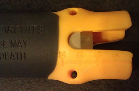
Comfortable, slip resistant grip.
The tool is comfortable in your hand, and it does provide a slip resistant coating. However, the best part of the grip is the constant reminder that you shouldn’t be working on live circuits.
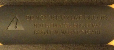
DO NOT USE ON LIVE CIRCUITS Not Insulated, misuse may result in injury or death
Conveniently fits in your pocket
Yes, it does fit in your pocket. But guess what Ideal… I want it to hang from my tool belt! Is it too much to ask for a key chain loop, so I can hang it from a carabiner on my tool pouch? I guess then they’d have to charge $5.50 for the tool, and maybe that’s too steep for the average DIYer.
All in all, this is a fairly nice tool. It would be a nice addition to any DIYers tool belt, er… pocket. It rips cable sheath really well, strips wires, makes terminal loops, and helps twist on wire caps. It’s a useful, sturdy tool, but I’m not sure I’m ready to give up my wire strippers just yet. For a DIYer looking for a useful inexpensive tool, this is a good solid choice. The Idea Lil’ Ripper Stripper gets 3.5 Captain Constructions, out of 5.

Tool Review: Ideal In-Sure™ Push-In Wire Connectors
A while ago I asked if push-in connectors were up to code. After determining they were, I checked the local Home Depot for these things every time I went. Then one day, bam! There they are. I grabbed an assorted 10 pack for ~$2.00, and ran home, filled with the type of excitement only a child feels on Christmas morning when he first lays eyes upon the bounty left by old Saint Nick. Admittedly, I was probably more excited than any grown man should ever be over this sort of thing.
Some may not know what Ideal In-Sure™ Push-In Wire Connectors are used for. Ideal In-Sure™ Push-In Wire Connectors, are devices used for joining two or more wires and insulating those connections. They can be used as an alternative to traditional twist-on wire caps (wire nuts), and require no twisting motion to create a solid connection. When using push-in connectors, the ends of the wires to be joined are stripped and pushed into the connectors. With traditional wire caps, the wires would have to be twisted together (mechanically joined) before twisting on the insulating wire cap.
Unlike twist-on wire connectors, it’s easy to remember how many wires can be connected with a single push-in wire connector. If you have a 2-port connector, you can connect any combination of 2 #18 AWG to #12 AWG wires. Using twist-on connectors, you’ll likely have to memorize or reference a combination chart.
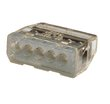
In-Sure™ Push-In Wire Connectors come in 7 varieties, so selecting the appropriate connector is easy.
2-Port
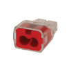
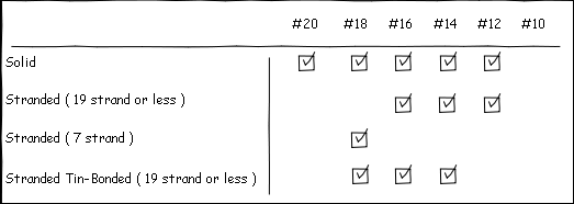
Acceptable Wire Sizes
3-Port
Acceptable Wire Sizes
3-Port Large
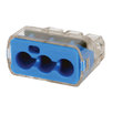
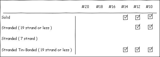
Acceptable Wire Sizes
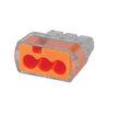
4-Port
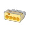
Acceptable Wire Sizes
5-Port

Acceptable Wire Sizes
6-Port
Acceptable Wire Sizes
8-Port

Acceptable Wire Sizes
Features
- No-twist connection reduces repetitive motion fatigue
- Low insertion force for fast and easy connections
- Compact size makes installation easy
- Clear shell gives visual verification of connection
- UL Listed to 486C and CSA Certified to C22.2 #188
- UL 467 Listed for grounding and bonding applications
- 600V maximum building wire, 1000V maximum signs and lighting fixtures
- Shell rated at 105 C (221 F)
Most old school electricians hate push connectors, due mostly to the crappy design of the first generation stab connectors on the back of receptacles. I, however, am more open minded, and will try anything that might make a job easier.
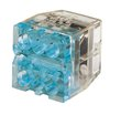
Once I got these things home, I did the only thing any reasonable and sane DIYer would do: I took one apart to see how they worked.
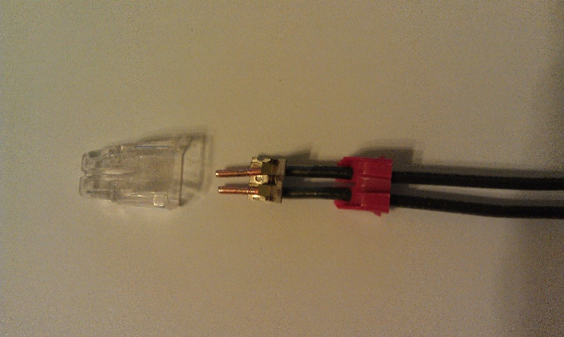
As you can see, they’re made up of three parts. The bushing (red), the contacts (metallic), and the insulating cover (clear).
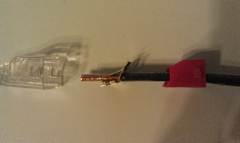
From the side, you can clearly see how the wires are held in place. And let me tell you, they are held in place really well. I yanked, tugged, pried, and pulled to try and get the wires to come out. So under normal circumstances, you shouldn’t have to worry about a wire slipping out. I did, however, find a way to remove the wires surprisingly easily. If you twist the wire back and forth while pulling, the wires will come right out. Doing so does damage the wire quite badly (you may be able to see the damage if you look closely at the above images), so it would have to be trimmed back and re-stripped before inserting it into a new connector. According to Ideal, twisting the wire to release it is a feature, not a bug.
When fully inserted into the connectors, the wires make a solid connection. So there should be no worry of resistive heating or arcing with these connectors.
Now I was satisfied the wires were not going to fall out, and I wasn’t going to burn down the house due to a bad connection. I decided to see how much time these things could save me in a typical situation. I wanted to see how long it would take to wire up a simple luminaire, first with traditional twist-on wire caps, then with push-in wire connectors.
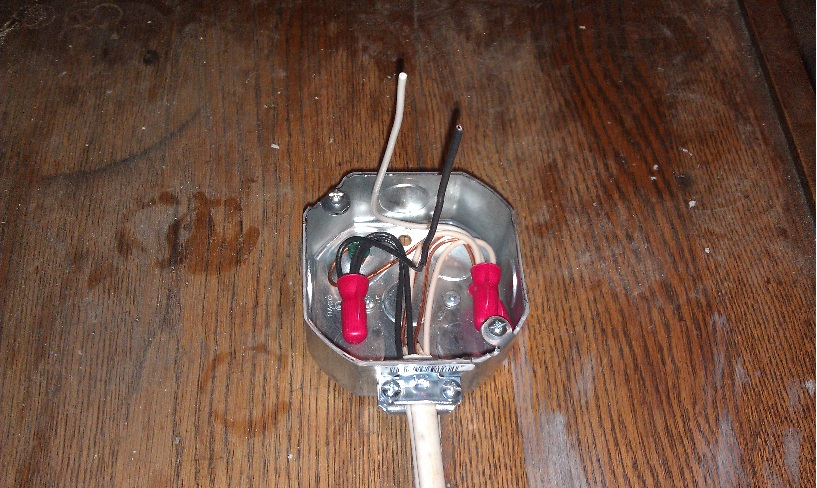
The Setup
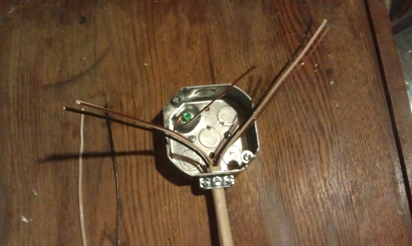
As you can see, I set up a typical scenario that electricians have seen many times. I have a feeder (from breaker), a feeder to the next fixture, and a couple pig-tails to connect the lamp holder.
Twist-on wire caps
The Procedure
- Strip wires.
- Twist wires together.
- Trim wires.
- Install wire cap.
- Repeat for each group of wires.
The Result
3:03.2
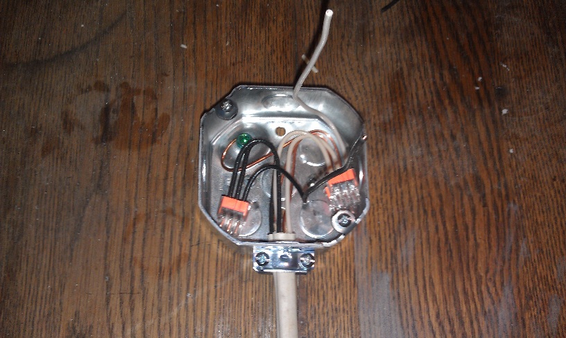
Push-in Wire Connectors
The Procedure
- Strip wires.
- Insert into wire cap.
The Result
1:50.5
For each luminaire I could save over a minute, using push-in wire connectors. That could be quite a time saver, if I was installing 10-20 lights.
The only fault I could find is that the wires can easily be twisted out of the connector. I don’t think this is a major issue; since the wiring would likely not see that much motion, but it is a small issue that hopefully Ideal can work out. They do cost more than the run of the mill twist-on wire cap, but the installation time savings could easily render that moot. All in all, I’d say these are a pretty slick product. I give Ideal In-Sure™ Push-In Wire Connectors 4 Captain Constructions out of 5.

Poles and Throws
No, we’re not talking Caber Toss here (I don’t have the legs for a skirt… err kilt… call it what you will, it’s still not a good idea to wear it while you’re working around the house).

We’re talking about switches! Specifically those found in your home, used to turn on and off lights and other devices.

First let’s start by defining a switch. A switch is a device for making and breaking the connection in an electric circuit. A switch can have one or many poles and one or many throws. All switches look about the same on the outside; a lever or button that is flipped or pushed, but internally the number of poles and throws determine how the switch is used.
In a switch, a Pole is the number of circuits that can be controlled by a switch. It might be easier to think of this as the number of inputs. Throws are the number of positions the switch can take. Throws can be thought of as the number of outputs (sort of).
Single Pole Single Throw (SPST)
A single pole single throw switch has one input, and one output. It is used to turn a circuit on, or off. “But wait…” you might be thinking “It turns the circuit on and off, isn’t that a double throw?“. You’re sort of right, I guess I didn’t explain throws so well. It’s not about the physical positions a switch can be in: up or down, it’s about the number of contacts in the switch. Maybe it’s easier to explain with a picture.

As you can see, there is one pole contact and one throw contact. With a SPST switch, turning on and off the light is easy.
Now that we’ve got the concept down, let’s take a look at some other types of switches. Keep in mind that you can have switches with as many poles and throws as you need, but we’re only going to focus on those typically found in residential wiring.
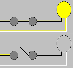
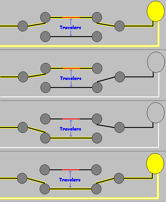
Single Pole Double Throw (SPDT)
A single pole double throw may also be known as a 3-way (2-way in Europe) switch. They are used to control a single device (light, string of lights, etc) from multiple locations. With this kind of switch, you can turn the light on at the bottom of the stairs. Then you can walk up the stairs and turn the light off at the top of the stairs. To do this, you’ll need two SPDT switches. One switch at the top and one at the bottom of the stairs. Internally they look like this:

As you can see, the single circuit can be switched between one of two contacts. In the US, these two contacts will be connected using wires called Travelers. These wires connect the contacts of one SPDT switch to the contacts of another SPDT switch (typically).

So how does this turn the lights on and off? Well let’s finish the drawing.
The power from the circuit is connected to one of the switch’s pole contacts, and the light is connected to the other switch’s pole contact. When both switches are in a similar position, electricity flows in the first switch, through one of the traveler wires to the other switch, and finally to the light.
“What if I want to control a light from more than two locations?” you might ask. Well, that’s where the next switch comes in.
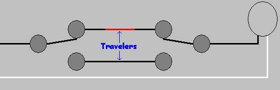
Double Pole Double Throw (DPDT)
Double pole double throw, also known as 4-way or intermediate switches, allow you to connect as many switches as you’d like into the circuit. Internally they look like this:

To control the light, we’ll add them into the circuit on the travelers between our SPDT switches.
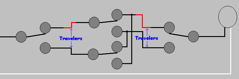
Now the current will flow into the first SPDT switch, out along one of the travelers to the DPDT switch, along one of the other travelers to the second SPDT switch, then finally to the light.
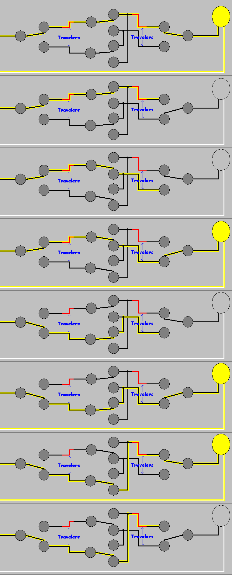
Using DPDT switches, we can control a device from as many locations as we want (within reason). All we have to do is add another DPDT switch, like so:
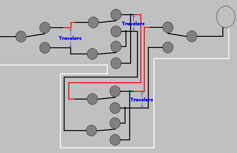
Understanding switches will help you whether you need to control a single light from one place or a group of lights from multiple locations. Anything you can imagine can be done, if you choose the right switch for the job. And please, no kilts while you’re working. It’s just dangerous.
Safer Than A One-Horse Open Sleigh
Electrical Safety
When preparing to put up holiday decorations, most people don’t think twice about plugging in all those twinkling lights. An open outlet just means room for more lights, an inflatable Santa, or dancing elves.
Then, you finish installing all the decorations, connect the final plug, and get 2 seconds of blinding Christmas glory followed by endless dark disappointment. You’re left standing in the snow holding the ends of two extension cords, mouth agape, wondering what just happened.
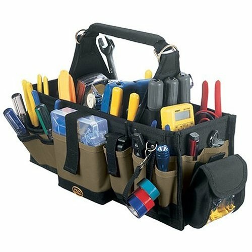
Well my friend, you know those things scattered around the house that look like this…?
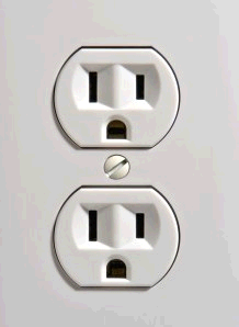
They have limits, rules, and even hidden dangers.
1440
When planning your holiday display (you do have a plan don’t you?), you have to consider more than just if Santa should be on the left of the gum drop forest or the right. You have to determine how much electricity you need, and how it will get to where you need it.
If you’re planning to power your display with a single receptacle, you’ll want to remember the number 1440. 1440 is 80% of the total wattage supplied by a 15Amp circuit, and the total wattage your decorations should use. Don’t believe me? Lets do some math…
First, the typical residential receptacle (in the United States) is on a 15 Ampere circuit at 120 Volts. So…
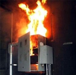
15A * 120V = 1800 Watts
This is the total wattage that can be used, before bad things start to happen. (Think evil fire demons.) So, to be safe, we’ll stay below 80% of the total wattage.
1800 * 0.80 = 1440 watts
See, told you I didn’t make it up.
“So I can hook up 1,440 watts of decorations!?”.
Hold on a second there, Jack. Remember I said “the typical residential receptacle is on a 15 Ampere circuit“? Well, it’s not likely it’s the only receptacle on the circuit. So to determine how much power you have for your decorations, you’ll have to figure out how much power other stuff is using.
The first thing you’ll have to do is find out what else is on the circuit. You might get lucky and it will be written on the door of the service panel. (For those unfamiliar, that’s the big metal box with all the big, funny switches.) If not, then the easiest way to find out is to turn the breaker off and see what stops working.
Now that you know what else is on the circuit, you’ll have to determine how much power is being used. Light bulbs are easy; they have the wattage printed right on them. For other things, there should be a label on the cord or near where the cord enters the device. Wait… What? You took the label off? Why would you do that? No matter, you should be able to estimate the usage with a chart like this Power Consumption Table.
Or you can use an ammeter to measure the actual usage.

To use an ammeter, simply clamp it around the hot wire leading to the device. If you clamp it around both wires, you’ll read 0. (Or at least you better measure 0, otherwise you have a problem). This will tell you how many Amperes the device is drawing, which can be used to determine wattage thanks to Georg Ohm. Here we go with math again…
Ohm found that Current (Amperes) * Voltage = Watts. He even made this cool wheel thing to help us out. (Maybe he didn’t draw it himself. How should I know? I’m not Wikipedia.)
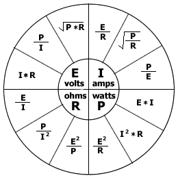
You can use this formula to figure out how many watts a device will use.
<device amps> * 120 volts = watts
Now that we know how much power is being used by other things on the circuit, we can figure out how much Christmas cheer we can plug in.
Simply subtract the total of all the devices from 1440.
1440 – <total wattage of other devices> = Remaining holiday joy.
Any Christmas decoration that consumes power, should have it’s power consumption listed on the box and/or the product itself. All you have to do is total up the consumption of the devices you want to use and subtract that from the remaining available wattage. This might be the hardest part, as you may have to decide which decorations are most important.
If you want to be able to connect more decorations, you could consider having a dedicated “seasonal” circuit installed. (You’ll need an electrician, and an empty space in the service panel for this.) I actually just did this myself.
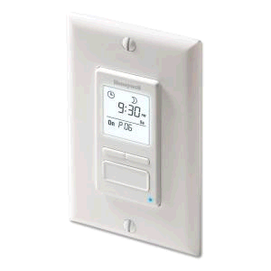
I installed a GFCI receptacle outside, in a weatherproof box (in the soffit of my porch). I decided to hook up to a 7 day programmable timer switch (for lights and motors), so I could control when the lights go on/off without having to remember to flip a switch (thanks to this question asked on DIY.StackExchange.com).
I had a new 15 Amp breaker installed in the service panel, and hooked the switch up to it.
Safely Connecting Santa
Now that we know how much stuff we can plug in, we have to be concerned with how we plug it in. To protect yourself and others from electric shock, all exterior Christmas decorations should be connected to a GFCI (Ground Fault Circuit Interuption) device. The GFCI will detect dangerous shock hazard situations, and turn the power off automatically.
Ground fault protection
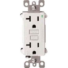
If you have your decorations plugged into a standard receptacle, you can upgrade the receptacle to a GFCI receptacle.
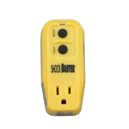
If you are using a lamp socket to outlet type adapter, you could use a Plug in GFCI device.
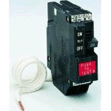
Another option, is to have the breaker replaced (by an electrician) with a GFCI breaker. This option provides protection to the entire circuit.
Extension cord safety
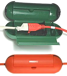
If you are using extension cords to power decorations, there are Waterproof extension cord covers available, that will make junctions water tight, and prevent the cords from easily coming unplugged.
If you have extension cords running across paths, where people will be walking, then you’ll want to cover the cord to protect it from physical damage and to prevent a possible trip hazard. It’s also a good idea to mark where the cord enters the path, and where it leaves it with flags. If snow falls and covers the cord, you don’t want to hit the cord with the snow blower. (While it may entertain your neighbors, it won’t be much fun for you.)
Wherever you have cord junctions (cords plugged into cords), you should take steps to prevent the junction from coming apart. This could be as simple as tying the cords together…
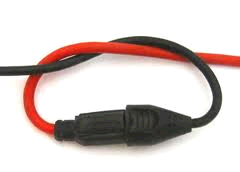
…or using a weatherproof device (see above), or physically attaching the cords to a structure using cable staples.
For more information on extension cord safety.
Protection at the plug
If cords are going to be plugged into a receptacle that is exposed to weather for an extended period of time, then you’ll want to get a outlet cover that is weatherproof, even when things are plugged in.

Summary
- Don’t use too much power.
- Protect yourself from ground faults.
- Run extension cords safely.
- Keep all electrical connections weatherproof.
Now that our plan is made. We know where everything will go, how it will connect, and where all the cords are. It’s time to get up on the ladder, and start hanging lights.
Ladder Safety
If you are using a ladder to hang holiday decorations, it’s important to follow a few safety precautions. Using a ladder unsafely could mean you’ll be spending the holidays on crutches or in a hospital bed.
Setting up the ladder
Height
The height of the ladder is the first point of concern. You want to make sure the ladder is tall enough so you can reach the work area comforatably, but not too tall that you won’t be able to position the ladder at a safe angle (discussed later). If you are going to be climbing onto the roof, you’ll want to make sure the ladder is long enough to reach at least 3 rungs (~36″) above the roof edge.
Stability
Make sure you place the ladder on a flat level surface, to prevent a tipping hazard. If you cannot find a level surface, you may be able to attach a ladder leveling product.

To make the ladder more stable, you can also purchase a ladder stabilizer.

These will not only make the ladder more stable, but also allow you to position the ladder against the house without crushing or damaging the gutters.
Angle
When positioning the ladder, you’ll want to make sure it’s at a 75° – 78° angle. The easiest way to determine if the ladder is at the proper angle is to stand with your toes against the bottom of the rails, then extend your arms strait out at shoulder height.
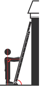
If your hands rest on a rung, your ladder is at a good working angle. If you can’t reach the rung, the ladder is at to shallow of an angle and you risk the bottom sliding out leading to a fall. If the rung is at your wrist or higher on your arm, the ladder is at too steep of an angle and you risk tipping backwards on the ladder.
Loads
Before stepping foot on the ladder, you want to make sure it is rated to hold your weight and the weight of any tools you may be carrying.
Working on the ladder
When working on the ladder you never, ever, want to overreach. Make sure you keep your torso between the rails at all times while working. If you can’t reach something, climb down, and reposition the ladder. It might be a little extra work, but it could save a trip to the emergency room.
If you are going to be getting on the roof, make sure the ladder extends at least 3 rungs above the roof edge. Always step onto the roof from a rung that is below the roof edge, and don’t ever step on a rung that is above the roof edge.
When working on ladders, it’s always good to have a partner, somebody to hold the ladder as you climb up/down. It’s also nice to have somebody around to set the ladder back up, if it happens to fall while you’re on the roof.
When climbing up/down the ladder, keep your hands free. Don’t climb the ladder with a hand full of tools; use a tool belt to keep your hand free.
For more information on ladder safety check out DIY.StackExchange How do I use an extension ladder to get onto my roof?, and visit Ladder Safety.org.
So! We safetly installed just the right amount of decorations without falling off the ladder, but how much will this awesome light display cost?
Calculating the cost of power consumption is fairly simple, especially since we’ve already determined how much power all the decorations use.
First we’ll start by figuring out how many kilowatts (kW) we are using, by dividing the wattage calculations from earlier by 1000 (1kW = 1000W).
<total wattage>/1000 = Total kW
Since the electric company charges by kilowatt hours (kWh), we’ll have to decide how many hours a day we’ll have the lights on. Then we simply multiply our kW calculation by the number of hours we have the light on.
kW * hours = kWh
Next we’re going to have to go looking for an old electric bill, so we can figure out how much the electric company charges per kilowatt hour (I’ll use the national average at the time of writing for examples below). If we multiply our kWh total from above by the $/kWh the utility charges, we’ll know how much it costs to run the lights for one day.
kWh * $/kWh = $ per day
Now that we know how much it costs for one day, we can simply multiply that by the number of days we’ll have the lights on.
$/day * days = Total cost
Lets figure out some examples, just to give you an idea of how much typical decorations can cost (calculations assume 8 hours per day, for 30 days).
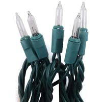 Incandescent mini string lights (50) = 20.4 Watts
20.4W / 1000 = 0.0204kW
8 hours * 30 days = 240 hours
0.0204kW * 240h = 4.896kWh
4.896kWh * $0.10 = $0.4896
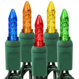 LED mini string lights (70) = 4.8 watts
4.8 / 1000 = 0.0048kW
8 hours * 30 days = 240 hours
0.0048kW * 240h = 1.152kWh
1.152kWh * $0.10 = $0.1152
 Oh yeah, we can’t forget the 12′ inflatable Santa Clause = 78 watts
78 / 1000 = 0.078kW
8 hours * 30 days = 240 hours 0.078kW * 240h = 18.72 kWh
18.72 kWh * $0.10 = $1.872
Just for fun, lets see how much it would cost if we maxed out our circuit.
1440 / 1000 = 1.44kW
8 hours * 30 days = 240 hours
1.44kW * 240h = 345.6kWh
345.6kWh * $0.10 = $34.56
Now that we’ve learned how to be safe while decorating for the holidays, the only thing left to do is enjoy the season.
Happy Holidays from all of us at DIY.StackExchange.com, and The DIY.SE blog team

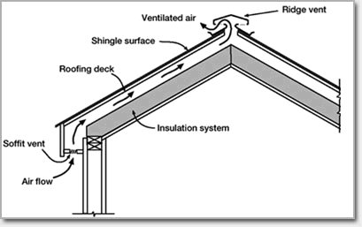
Resuscitating the roof: Providing adequate roof ventilation.
Proper ventilation is an important; often overlooked, contributor to roof health. Controlling the temperature of the roof with ventilation will increase the life of roof coverings (e.g. shingles), as well as help prevent roof damaging problems like ice dams.
To control the temperature of the roof, ventilation is key. You’ll want outside air to be able to flow along the underside of the roof, and warm moist air to be able to escape from under the roof. “But wait… I want to insulate my roof to keep my heat in” you might say “How can I insulate the roof, and still keep proper air flow?“. Hold on to your britches, we’ll get to that. But first, we have to talk about roof vents.
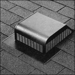
Roof vents
When the sun beats down on the roof the roof becomes hot (obviously), this heats the air under the roof. Our first step to ventilating the roof, is to get this hot air out from under it. We can get some help here since warm air is less dense than cold air, so it will rise naturally. To allow all this rising air to escape, we’ll want to install some roof vents. These can be either a vent on the face of the roof near the ridge,
or a Ridge Vent.

Roof vents come in all shapes and sizes, so it shouldn’t be a problem finding one that looks good on your house.
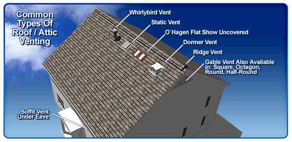
So now we have a way for the hot air to escape from under the roof, but that air has to be replaced by air from somewhere else, right? That’s where Soffit Vents come in.
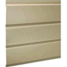
Soffit (Eave) vents
Soffit vents can be actual vents; like those you would see on the walls or floors of a home with forced air heating,
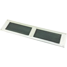
or slits or holes cut into the soffit covers themselves.
These allow cooler outside air to flow up under the roof, to replace the warm air that is escaping thought the roof vents.
“But I still want insulation in the roof! How can air flow from the soffit vent to the roof vent, if I have insulation?“. Alright, don’t get so excited. This is where baffles come in.
Baffles
Baffles are long U shaped pieces of plastic or foam, that are secured to the underside of the roof decking between the rafters.

They allow air to flow freely between the roof and the insulation under the roof, by creating an unrestricted channel under the roof decking. This allows you to install insulation in the roof, while not blocking the flow of air under the roof.
Baffles are installed by nailing or stapling them to the underside of the roof decking, between the rafters like this.
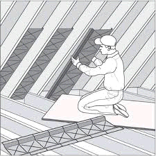
The baffles can then be covered with the insulation of your choosing.
If you are not going to install insulation in the rafters, you may only have to install baffles at the lower end of the roof or not at all. You’ll want to make sure air can get from the soffit vents into the rafter voids, so you may need short baffles to run from the soffit past the insulation in the joists of the attic floor. In this case, the baffles do not have to run the entire length of the rafter void.
Let the air flow
OK, so now we have cool air flowing into the soffit vent, warm air coming out the roof vents, and an open passage to allow the air to flow from soffit vent to roof vent.
“But how does that make the roof healthier?” you might ask. Well, now that you have good ventilation the roof will stay cooler in the summer (hot months). This will help the roof covering last longer, by preventing it from getting as hot as it would without ventilation. In the winter (cold months), ventilation will keep the roof colder helping to prevent problems such as ice dams.
Ice Damming
Ice dams form when snow melts on a warmer section of roof, the water then flows down the roof until it reaches a colder section of roof (usually above the soffit) where it re-freezes. Eventually the freezing water will create a ridge, which will catch more water, which creates a larger ridge. Until finally, you have a dam of ice that prevents water from draining off the roof.
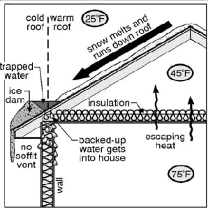
Once this happens, water can backup under the roof covering leading to water infiltration.
A happy roof, makes a happy homeowner
So, now that you have good roof ventilation. Your roof coverings should last longer, and the house should be slightly cooler in the summer. Ice dams, and dangerous icicles will be less likely to form. And you’ll likely notice savings in your heating and cooling bills, which is always a good thing.
Home Improvement Blog on Google+
Home Improvement Blog on FaceBook
Bloggers Wanted
Latest Articles
Topics
- Electrical (8)
- Introductions (7)
- Plumbing (3)
- Projects (13)
- Repair (4)
- Safety (5)
- Tips and Tricks (5)
- Tool Review (5)
- Tools (6)
- Uncategorized (5)