Projects
Kitchen Renovation – Moving to Open Concept
This is part two of a series.
For part one, read Kitchen Renovation – Introduction and Footings.
The previous installment dealt with the building a new footing to support the interior end of the beam. When I last left you, I had posted a picture of wet concrete in a hole. As luck would have it, that wet concrete soon became dry, hard concrete. I watered it a couple of times to help it cure, and waited the prescribed 5 days (warm weather) curing time before loading it. Installing the posts was relatively simple. Cut 2x4s to length, hammer them into the bracket, and bolt them together. Well, it should have been simple. The problem was that 5 2x4s makes a post 7 1/2 inches. I had a stud that I really didn’t want to demolish at about 16 inches on either side. My drill, with a bit long enough to penetrate the post, was just too big to fit in that stud bay. The idea occurred to me that I could use a shorter bit, and by drilling the holes with absolute perfection, have them meet somewhere in the middle. However, that involves more precision than I am capable of; so I nixed that idea right off the bat. I ended up using a short, 3/8 spade bit to start the hole, and when I had gone in a couple of inches, stuck the long bit in the hole, wiggled my drill onto the long bit, and using some severe bodily contortions, managed to tighten the chuck. Then I finished drilling.
Now that the holes were drilled, it should have been a simple matter of slipping the bolts in and tightening the nuts. Not quite. There was a new problem. An 8-inch carriage bolt doesn’t quite make it through 7 1/2 inches of post when the 2x4s aren’t exactly tight together. I grabbed a couple of bar clamps and tried to move everything, but it just didn’t work. Road Trip! Off to the the blue store! At the blue store, I bought a ten inch bolt. I stuck it in, and nutted it tight, and everything came together tightly — tight enough that the next hole now took the 8 inch. Working up, I pulled the post together, and when I was done, took the ten-incher out and replaced it with and 8. I’m sure I could have returned the long bolt, but I had used it, and decided not to.
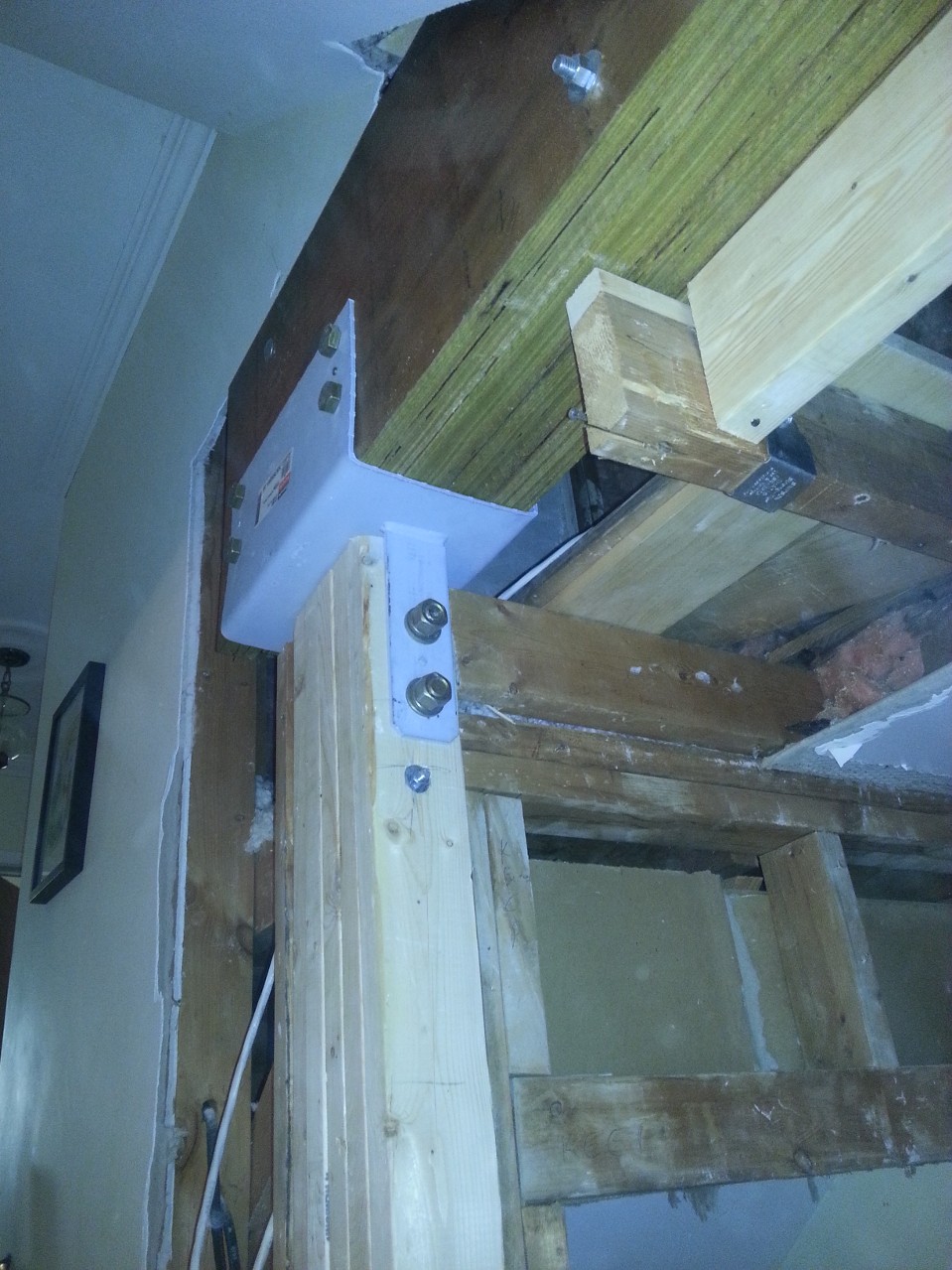
I installed a bit of blocking at the top, used structural screws to the header, and 10d nails into the bracket at the bottom. Once everything was done, it felt really solid. I’m not a structural engineer, but sometimes you can just tell that something won’t fall down. This won’t. Unfortunately, I was rather neglectful in the camera department, so all I have is a picture of the top of the post.
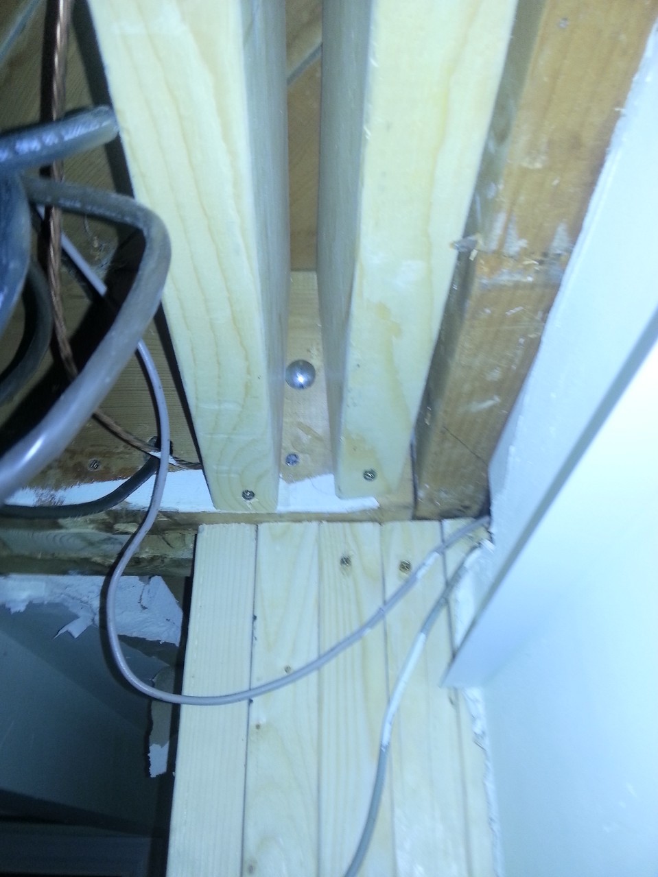
Top of basement post.
Next Step: Prepare for the post at the other end.
This one should have been simpler. I had a lot more room to work, having cleared out a couple feet of plaster on either side. The plan called for a single 8″ bracket, drilled into and epoxied to the top of the foundation wall. I had a sneaking suspicion that the foundation wall might have been hollow block, which would have required me to fill a couple of courses with concrete before mounting the bracket. Luckily, I was wrong. It was a solid poured foundation and it was wide enough for full bearing. Simple! All I need to do is drill and slip in my bracket. What I didn’t consider, and neither did my engineer, was that all those joists had to end up somewhere. In particular, the 2×8 double joist that was supporting the existing wall would probably be resting on the foundation wall right where I wanted to put my post! There was a third joist a couple inches away, and the space between was filled another bit of 2×8. So I opened up my finest drafting tool (MSPaint) and put together a quick sketch to email to the engineer:
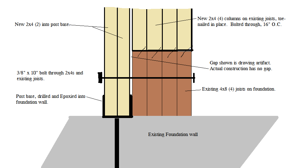
Revised plan for exterior wall post.
That email was sent off, and my wife and I went out to a friends for 1 pound striploins, many kilos of wine and several of Fidel’s finest exports. The engineer got back the next day and approved my revision. Road Trip! This time, to the orange store, which rents tools. I rented a concrete drill and bought a tube of concrete epoxy. It took about 3 minutes out of a 4 hour rental to drill the hole. I cleaned the hole out with the shop vac, squeezed in the tube of epoxy, and stuck the base in. I quit there, figuring we’d put the post up on beam day. Besides, I had a whole lot more work to do.
Demolition:
Once again we enter the realm of lower skilled labour. My contractor is booked solid over the summer, and can only give me a day here and there for jobs that I really need him for. Swinging a hammer at old plaster walls isn’t a valuable use of his skills. So I did it myself. First, I put 6 mil poly and duct tape over every door in the house. I had learned from the small amount of demolition that I had already done for the front post, that dust gets everywhere. Turns out I needn’t have bothered. Dust got everywhere anyways. I did have the foresight to put big shipping bags over all the furniture that was too big to move out, and laid the 6-mil over the wood floor. Then I spent two days swinging a sledge, prying and reciprocating away the plaster walls. Not fun work, but also not work I want to pay top dollar for. A second person would have been useful to make trips to the dumpster, but I didn’t want my spouse becoming concerned over the mess I was creating. The only point of interest is that plaster is messy, and some genius thought it would be a brilliant idea to put wire mesh on ever corner, both inside and outside, nailed about every 2 inches. I suppose it was meant to last, and it did last for 50 years, but I wanted it to no longer last. I also ran into something the previous owner had done himself. At one point he had installed some off the shelf cabinetry, and added a couple more cabinets than the original builder had. This meant that the bulkheads didn’t quite match up. So he boxed them out with plywood. The only problem was that he was a frugal man. The type of penny-pinching gentleman that saves every screw he has ever removed in a jar. Well, he used those recycled treasures on this project. It took five different screwdrivers to pull them out: two sizes of Phillips, red and green Robertson and a slot. I saved those screws, and will use them to install something just before I sell the house. He actually did a good job of it. Everything was tight and square, and there was no room to squeeze in my reciprocating saw with a metal blade to cut them off.
At some point in there, my brother-in-law and his wife came over to help Anna pack up the cabinetry, and destroy any cabinetry that we could get away without. I also made some trips to the specialty lumber yard to order parts. I needed a couple of big nasty metal brackets to connect the beam to the posts. The load should be bearing down on the posts vertically, but we need something that can handle a bit of torque or the whole house collapses like this: / /. I also needed to order the beam, which was 4 plies of 16 inch by 1 3/4 inch LVL. The parts I needed, while standard in the catalogue, are actually made to order. This meant some delays, but the Simpson Strong Tie plant is only a 15 minute drive from my place, so I saved some time by picking them up rather than waiting for delivery. I also went to the bolt specialty store to pick up big 3/4 inch by 8 inch bolts at 8 bucks a piece.
Also somewhere in there, I spent a day and a half moving electrical circuits away from the wall to be demolished. Unfortunately, the orange store did not have wire stretchers available for rent, so it involved purchasing junction boxes to put in the basement drop ceiling or attic for splicing purposes. Only three orange/blue trips. Managed to snag a 20 m roll of 14/2 off of my next door neighbour who literally just happened to be carrying it out of the house to my bin (with my permission), as she was cleaning up her late husbands workbench. The fun work begins:
Wiht all the prep done, it’s now that most joyous of days! Beam Day! My contractor, Adriano and his buddy Franky showed up, with a truckload of tools, when they said they would, with a cup of Tim Horton’s each. On time and pre-coffeed. These are responsible contractors. They took 15 minutes to look at my plans, look at my parts, and took off to the orange store to buy big honking drill bits. Half an hour later, they were back, ready to work.
The first thing we did was install the post at the front, and mount one of the big ECC brackets. Then more of the same at the other end. IMPORTANT: Everything takes longer than you expect. Cutting, drilling and bolting 5 2x4s together should only take 10 minutes. Wrong. It’s more like 30. Then drill 2 8-inch by 3/4 inch holes for the bracket bolts. About 15 minutes each. Between Adriano’s drill, Franky’s drill and my drill, we managed to not heat them up too much. Adriano did one end, Franky the other, and I ran around and did what I was told without getting in the way. Once the post and brackets were up, it was time to install the beam.
We live in a back split, and are very fortunate (for this job) to have fantastic access to the the attic. Through the wall — not the ceiling. But, even with that, there was no way we were going to be able to manouevre a 23-foot long beam to that access door. Particularly since we only had 20 feet to the back of the house. Adriano went into the kids’ room, and took out a window. Something I never would have had the courage to do. (For fear of breaking the glass or slicing my hand off.) Franky and Adriano fed the beam segments up to the second floor window, while I grabbed and got it into the house to a balance point. Then I could hold it while the guys ran upstairs to feed it in the rest of the way. The first three segments went in easily, the fourth required a bit of “encouragement”. But we squeezed them into the brackets. We now had 4 plies in the brackets — and it was only 10:30. This job would be done by noon! Franky screwed a 2×6 across the joists parallel to the beam so we could use a pry-bar to straighten the beam, and temporarily screw it the the joists to keep it straight. (Important: do this before bolting to the brackets.)
All that was left was to drill 8 3/4 inch holes, 24 1/2 inch holes, bolt everything in, and nail up the joist hangers. That took another 4 hours. Plus a trip to the blue store for more nuts and nails. At 2:30, it was time to test our creation. Franky and Adriano went at the stud wall with sledges and pry-bars and got rid of the of the offending lumber while I ran back and forth to the dumpster. At 3:15, there was a mass rush with brooms, garbage cans and the shop vac, while we fought over the ownership of tools. Actually, sorting out tools was easy. I had designated 3 areas beforehand so that each person had their own storage. Other than a couple of drill and impact bits that we were exchanging freely, everyone respected the zones.
3:45, beer on the back patio, while I counted money out to the boys. They earned every penny. There was no way I could have done this job with a couple of unskilled buddies and a case of beer.
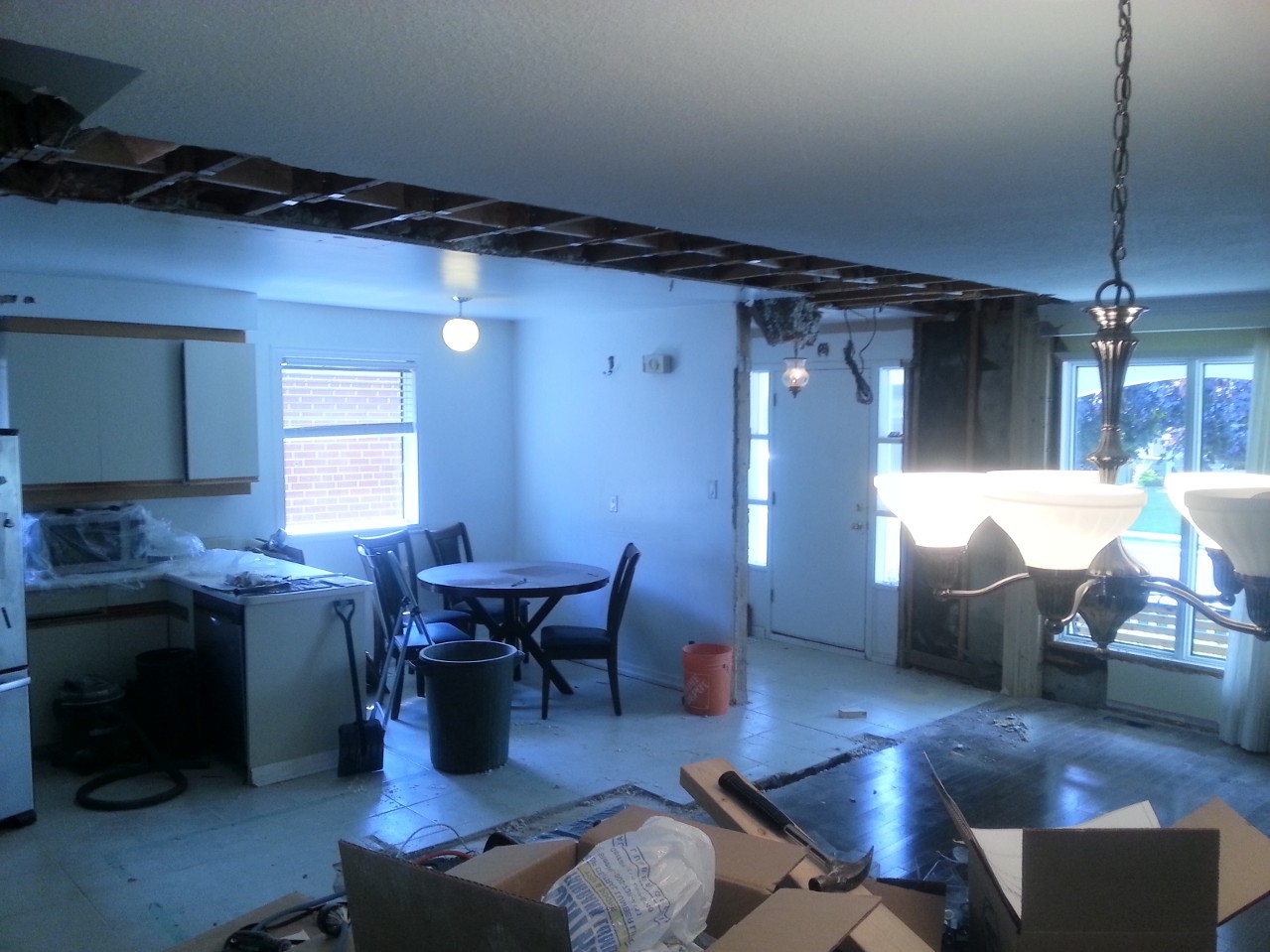
The Money Shot!
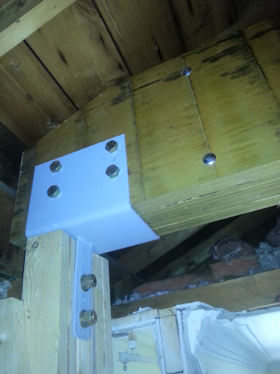
Post and Beam connection against exterior wall.
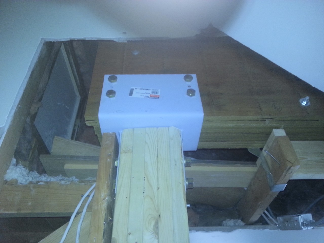
Post and Beam – Interior
Post and Beam Interior
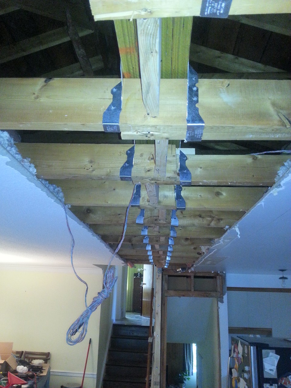
Joist hangers
Why we did this
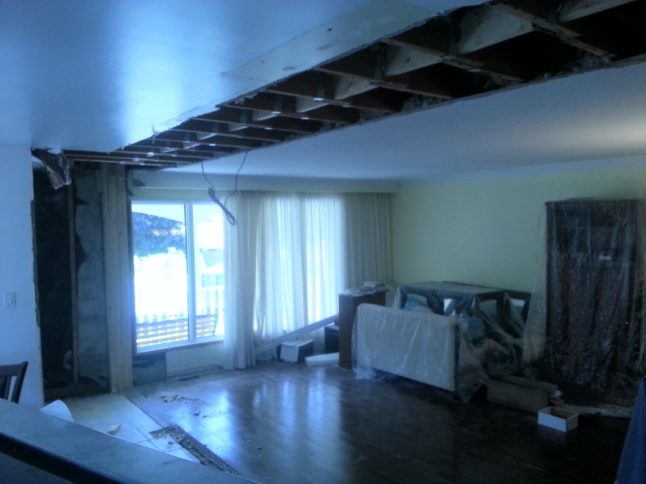
Reverse angle
Anna was thrilled when she came home. We had finally achieved the open concept that we wanted. Well worth the effort.
The question I know you all have is “Was he properly attired during all this work?” I’ll leave you with this photo, salt stains and all:

Next Up: Flooring, Kitchen and more demo.

Kitchen Renovation – Introduction and Footings.
Lifestyles have changed. In a 1950s Leave It to Beaver world, urban people had very clearly defined roles. Dad would entertain the guests while Mom hid in the kitchen preparing a meal. Design reflected that. Kitchens were viewed as utilitarian areas in which guest were not to enter.
1960s and 70s design at least acknowledged that families would often eat in the kitchen, and more space was provided to accommodate a kitchen table.
Some time in the 80s and 90s the kitchen evolved into a more public space. Guests would gather and even help out in the preparation of a meal. The drawback was that seating was often uncomfortable.
More recently, the trend has been to open concept kitchens. This design philosophy often puts the kitchen right next to a dining/living room without a wall separating them. It allows the guests to sit comfortably on a couch, have drinks and snacks on the coffee table while still allowing interaction with the people in the kitchen working on the meal. It fits in with a more modern lifestyle.
Our house was built in the 60s. We have a 20′ x 10′ kitchen separated from the living/dining room (24′ x 14′) with a central supporting wall. We finally decided that that wall has to go.
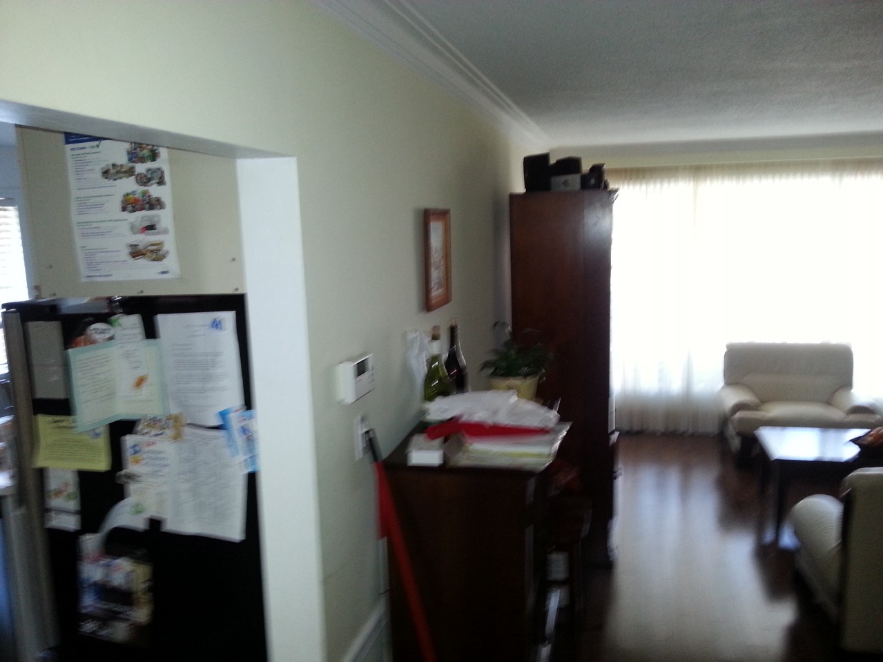
One end of the wall to destroy
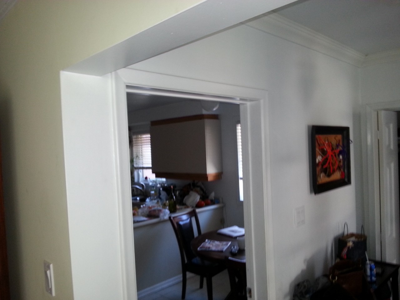
The other end, with a glimpse of our lovely 80s cabinetry
Also on the list is updating our extremely dated cabinetry, which had been installed by the previous owner, probably from off the shelf cabinets. Hinges are going, finish is chipped. The laminate counter-top is swelling up in the humidity making it nearly impossible to open some of the drawers. Corner Cabinets require me to change into my spelunking equipment in order to find anything. We need an update.
So, the plan is:
- Remove dividing wall.
- Re-tile the floor.
- Replace the cabinetry.
- Re-wire so that we can make coffee and dry our hair at the same time. (Bath and Kitchen are on the same breaker)
- Install a fume hood (requires moving the stove) from an internal to an external wall.
- While the cabinets are gone, stud out the uninsulated exterior wall and put some pink stuff in there.
- Do a fantastic job, as cheaply as possible. Hire experts where needed, DIY where we (I) can.
We shopped out the cabinetry and designed the new kitchen ourselves. Next step. Call an engineer to figure out how to get rid of that wall.
Fortunately, the wall isn’t carrying a heavy structural load, but the ceiling joists are lapped on top of the wall, and they support the ceiling plaster, insulation above, and any light fixtures. So we can’t just knock down the wall, or the ceiling will collapse into the center of the house.
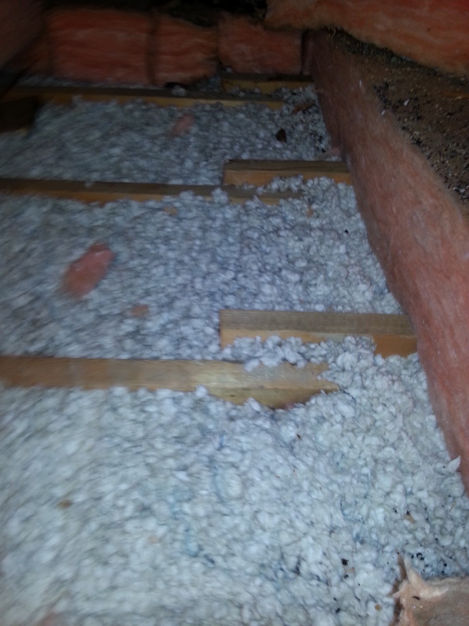
Lapped ceiling joists…
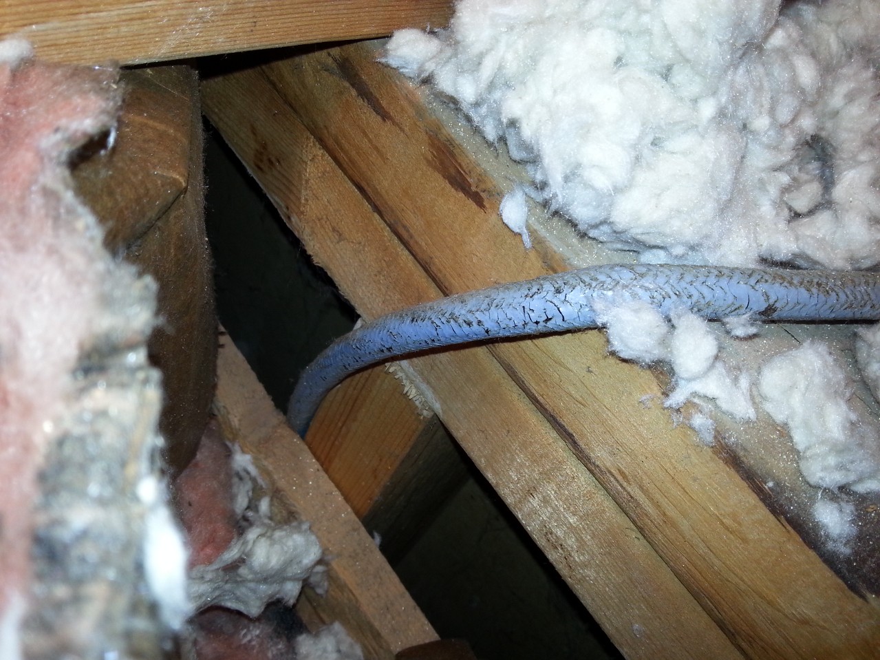
On top of this stud wall
The solution is to install a beam to take the load off the wall, and then knock down the wall. The problem is that the existing stud wall carries a linearly distributed load. A beam, being supported at the ends only, will put the load onto two points. Consequently, these loads need to be tied into the foundation.
Step 1: Footing.
The post at the front of the house is relatively easy. It will rest on the foundation wall, which is (I assume), hollow construction blocks. I’ll simply need to fill them with concrete, a couple of blocks deep, and stick in some column base connectors while the concrete is still wet.
It’s the other end that’s the problem. I need to dig a new footing. The engineer specified a footing of 22″ x 26″ by 14″ inches deep, with a 15 mm @ 4″ spacing rebar grid, 2.5″ below the surface.
Now, digging is traditionally used as an example of extremely unskilled labour. “But the world needs ditch diggers too!” is often used as a rallying cry against sending everyone to university. Unskilled labour? I’m highly skilled at unskilled labour. This is right up my alley, and a job I can save money on.
So I started digging. This isn’t as easy as you think, because the floor is concrete. I made several false starts. I tried drilling holes with a masonry bit to create some break lines. It worked somewhat but was tediously slow.
Next I took out a mason’s hammer, with a pick on one end and just started whacking away at the center of the field. It was slow and tedious, but eventually I managed to break away a hole big enough for my hand. It was about 3 inches thick. Certainly not enough to support a load. I dug out some of the gravel underneath, and managed to whack away with a small sledge. Eventually, with a combination of under-digging and sledging, I got a rough opening dug. Then I used a sledge and chisel to clean up the edges. Concrete went into plastic pails, and were carried upstairs to the dumpster.
Digging out was much more difficult than I had imagined. I’m sitting on top of some of the hardest clay imaginable. In the end, I resorted to picking at it with the pointed end of the mason’s hammer, and scraping of 1″ thick layers with a hand trowel. Soon I ran into a problem. There was an old footing in my way.
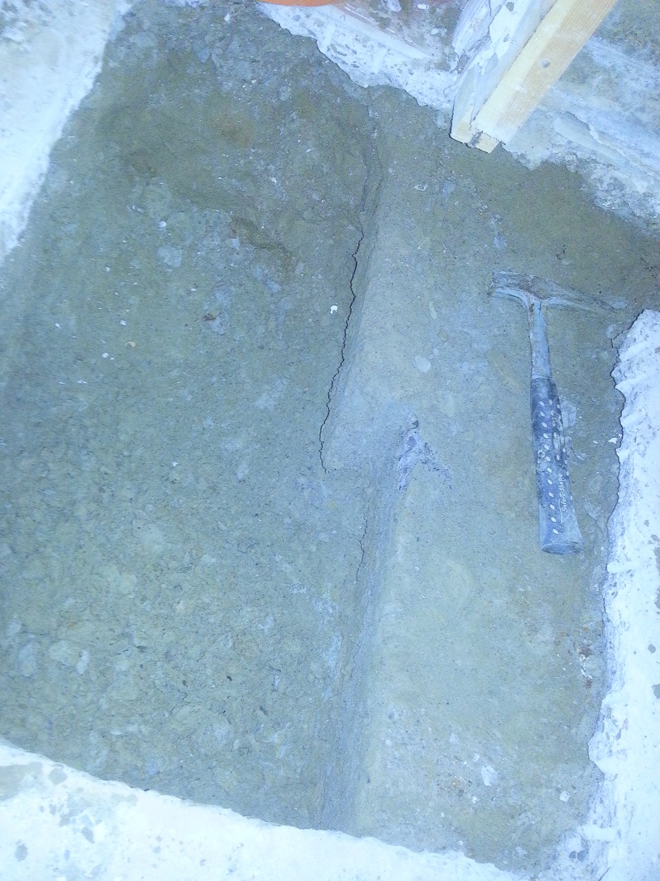
Evil Old footing that is both useless and in the way.
This was 5″ thick, no where near enough for my engineer’s needs and just too thick for me to hack away with with the sledge or mason’s pick. Time for a trip to the rental store. I picked up a handheld demolition hammer (mini-electric-jackhammer) and went nuts on the concrete.
It also did a trick on the clay, allowing me to shovel it out rather than troweling it. Things went mighty smoothly. Fortunately, I had a nagging suspicion that there might be a clay sewer pipe in there somewhere. The last thing I wanted to do was crack it, so I went very carefully, probing with a thin rod, and hand digging around anything solid I found.
There was a clay pipe, and it was in the corner by the hammer head, about 12 inches from the surface. I did not break it. Infantry mine sweeping training comes in handy sometimes.
Next, I lined the hole with 6 mil poly, and threw an inch of gravel on top of that.
Meanwhile, my metal-working buddy was building the rebar for me. The main problem was that the engineer specified 15 mm bar, which is impossible to bend. 10 mm, I could have stuck in a vise, but 15 mm is just too much. He bent it in his massive hydraulic brake.
The rebar cage was made with 10″ legs, as per design. However the design also specified that the top of the cage should be 2.5″ from the surface. When I stuck it in the hole, It ended up 5 inches too low. In order to solve this problem, I ran a couple sticks of scrap lumber across the hole, and suspended it from them with mechanics wire. Good plan, as it allowed me to finely adjust the height.
Some time earlier, I put the call in to the inspector. In my jurisdiction (Toronto) All holes must be inspected by a city employed hole inspector before you make them not a hole anymore. This is actually a good idea. The building department’s job is to verify that you are following the plan. The only way they can tell, is if they see the hole as a hole. If it’s full of concrete, they have no way of knowing whether it is the proper depth, or if the rebar is even there.
Shortly after I wired the rebar in, the inspector showed up, looked at my plans, said “Yup, It’s a hole. You’re good to pour.”
After 7 paragraphs of my regaling you with tales of my hole emptying experience, you probably can’t handle that many of my hole filling experience. So I will be brief. 11 bags of concrete were mixed 2 at a time, carried downstairs, and dumped into the hole. A piece of scrap rebar was used to jiggle and poke it so that it got into the corners. I smoothed off the top, and inserted my column base. And my footing was done:
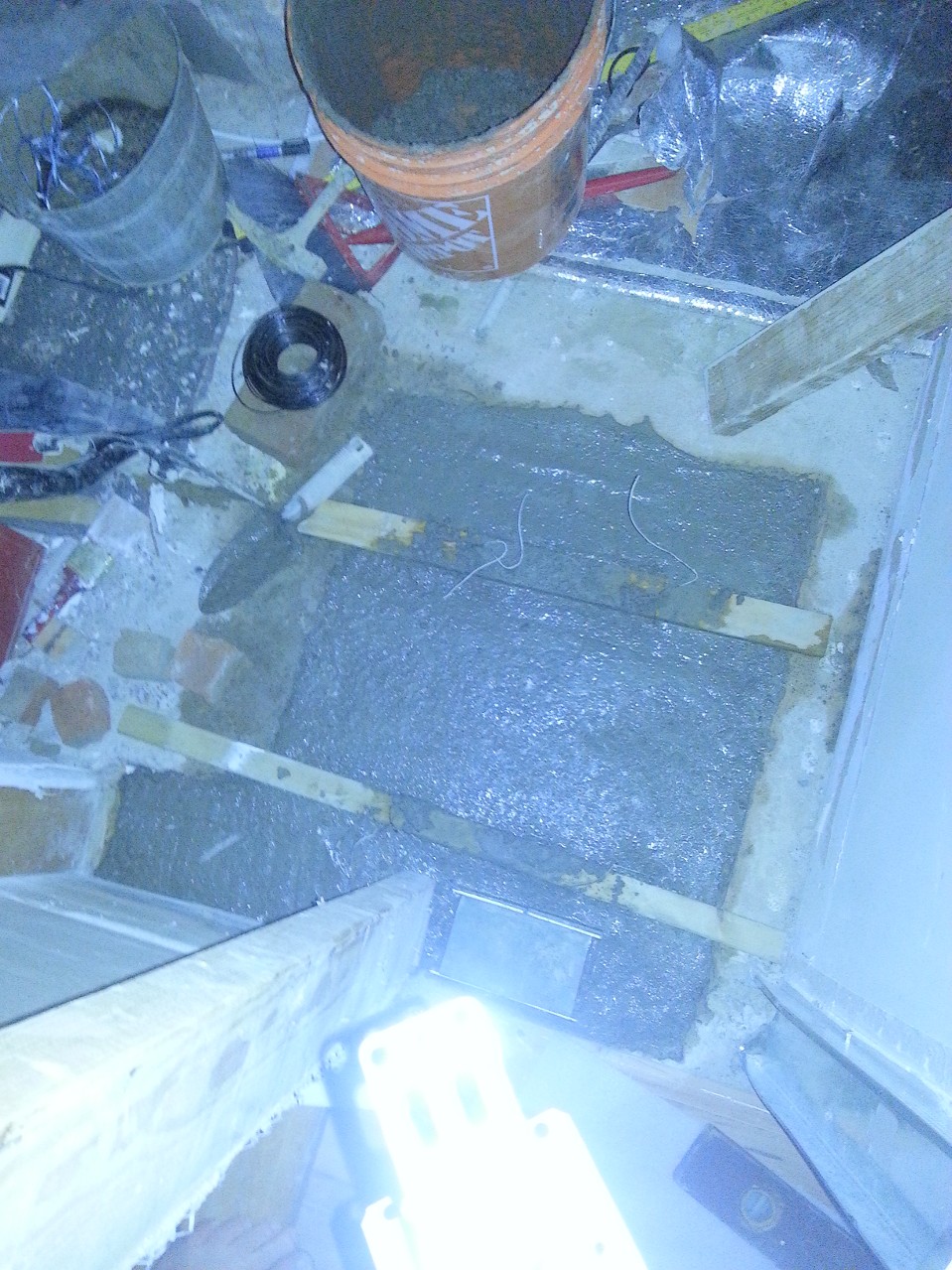
Finished footing
Next on the list: Attach the columns and smash plaster off the wall.
I’ll keep you posted.
Tiling a Fireplace Surround
THE SETTING
Our 1869 foursquare farmhouse had been renovated around 1905 to make it more “upscale and modern”. The front and back parlors were joined and a fireplace was installed. In 1999, the house again got a makeover, with new beams, plumbing, wiring, but maintaining much of the molding, windows, and style from the turn of the 20th century.
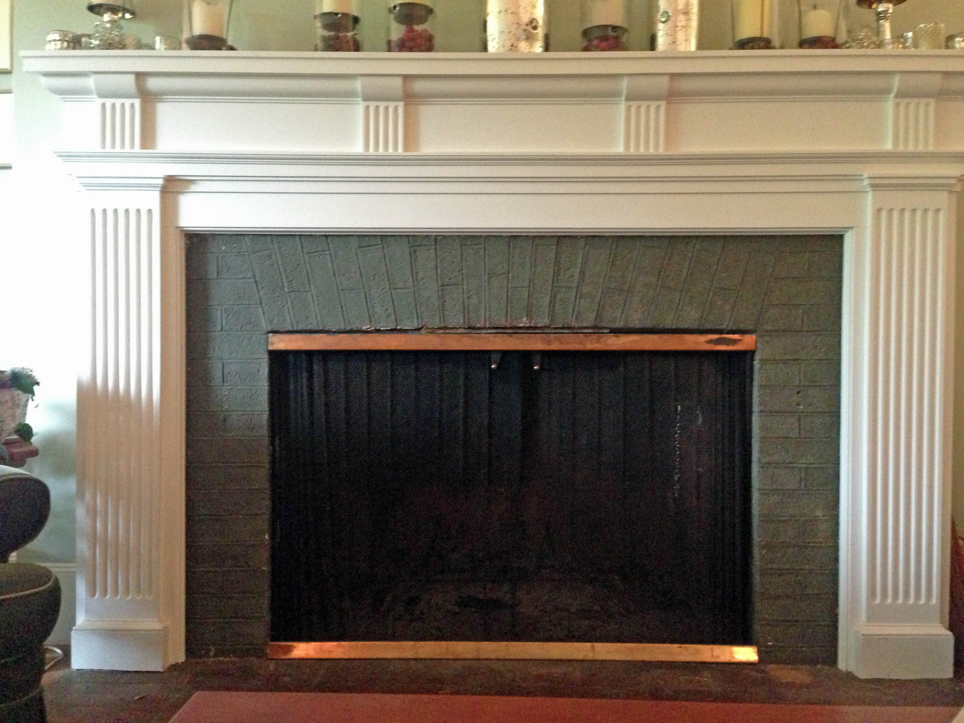
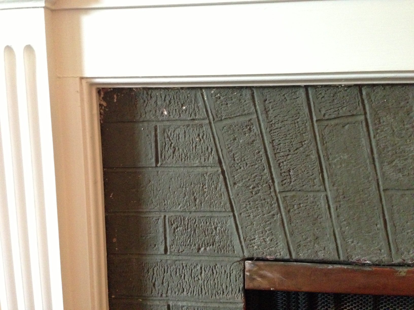
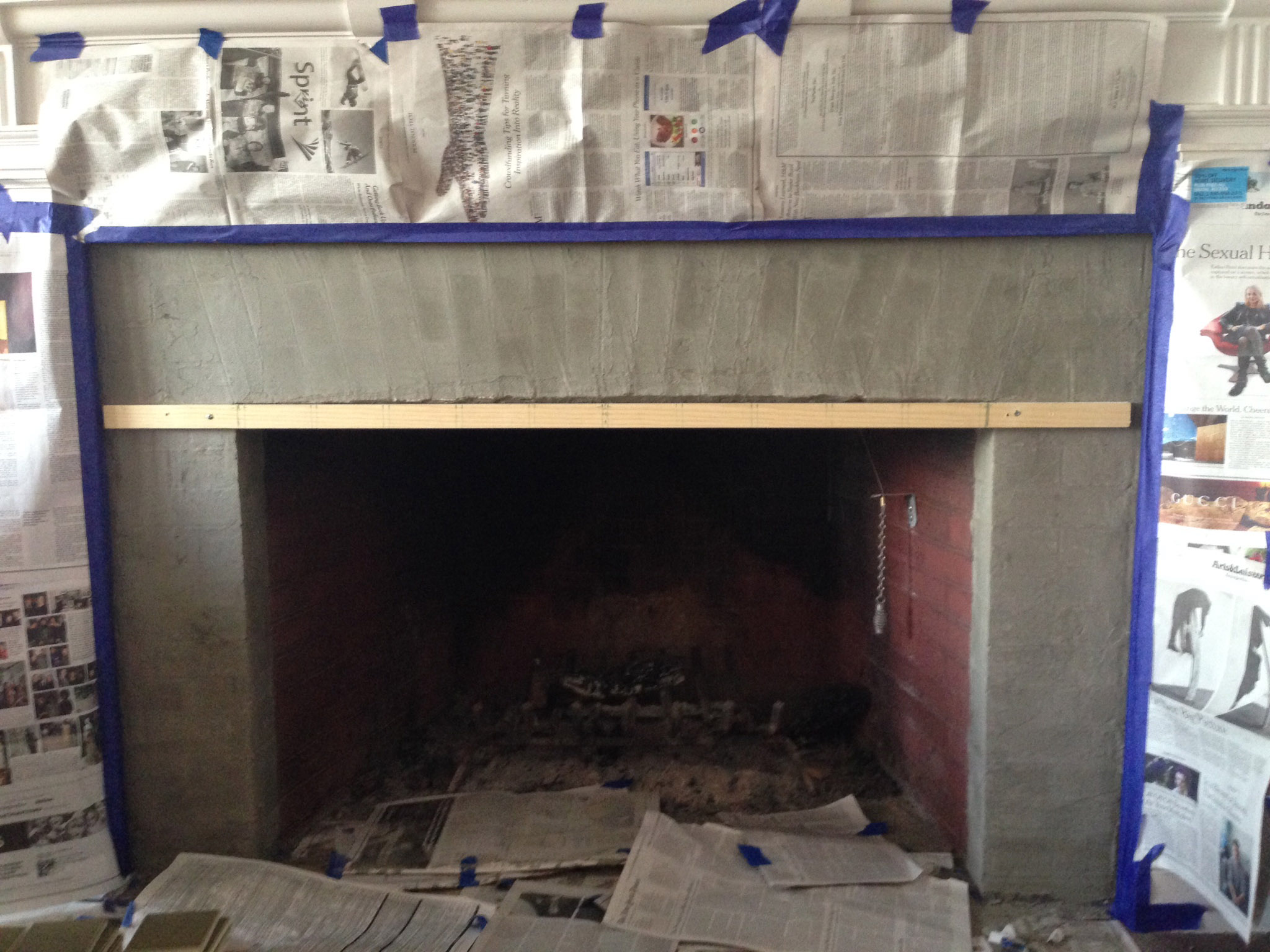
The fireplace now consisted of a painted wooden mantle and trim, with a brick façade around the firebox. The façade had been painted several times, but seemed fairly sound. It was now a dull, dark greyish green. Time for a freshening up.
DESIGN
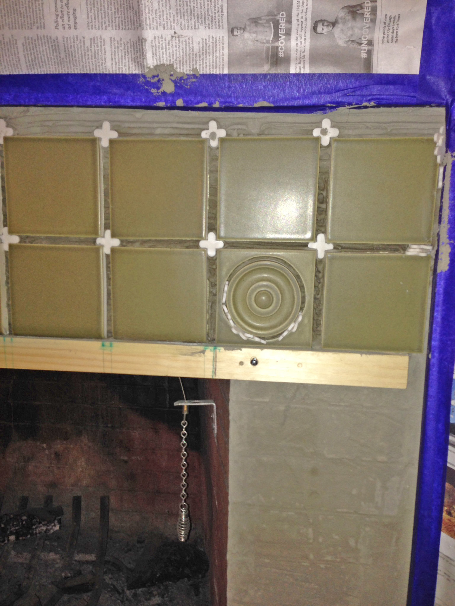
We decided on tile, selecting an arts-and-crafts style that would have been in keeping with early 1900s décor. The 4 ¼” x 4 ¼” tiles were handmade in California. We chose field tiles (regular four sided tiles), bullnose tiles (with one sloped finished edge) and a few decorative bulls-eye tiles for accents. The tiles were about 1/2” thick and slightly irregular, with no built-in spacers.
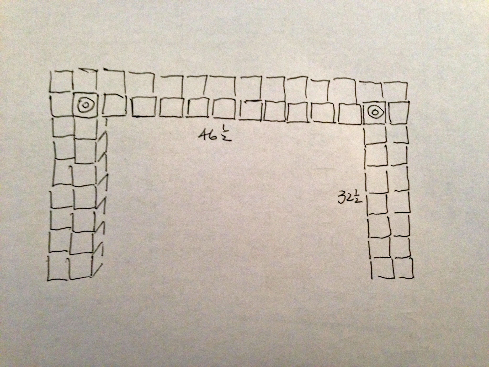
The layout worked out fortuitously. We wanted wide grout lines, often seen on arts-and-crafts projects. We also wanted decorative tiles on the inside corners where the vertical and horizontal runs met.
With the moldings closest to the façade removed, and with a careful adjustment of the grout spacing, we were able to get a pattern that gave us two columns wide on the sides and two rows deep on the horizontal section. We wanted only full tiles between the decorative corners, but the 48″ spacing between the inside edges of the firebox was a bit too wide for 10 tiles, even with 3/8″ grout. Stretching them out was not an option because the grout lines would be too wide compared to the vertical runs. So we decided to add tiles to the vertical inside edge of the firebox. This narrowed the horizontal opening by about 1½” ( the thickness of two tiles and thinset), down to an overall width of 46 1/2″ . With just a little fudging of the grout width to a hair more than 3/8” (but not quite ½”), we got a satisfactory fit of ten tiles horizontally between the bulls-eyes.
PREPARATION
Getting ready for the installation, we took a closer look at the brickwork, only to find that it was not. The sloping angle of some of the “brick” corners should have been a giveaway. This was actually stucco that had been textured and grooved to look like decorative brick.
As I begin each DIY project around our house, my wife asks “Have you ever done this before?” the unstated, but obvious worry being that I was going to serious wound myself, set the place on fire or cause a giant sinkhole to swallow up our homestead. My usual answer is a smug, silent look, implying that, beyond question, I am up to the task. But his time, I actually hadn’t done ceramic tiling before. Time to start reading, surfing the web, and asking my good old friends on diy.stackexchange.com.
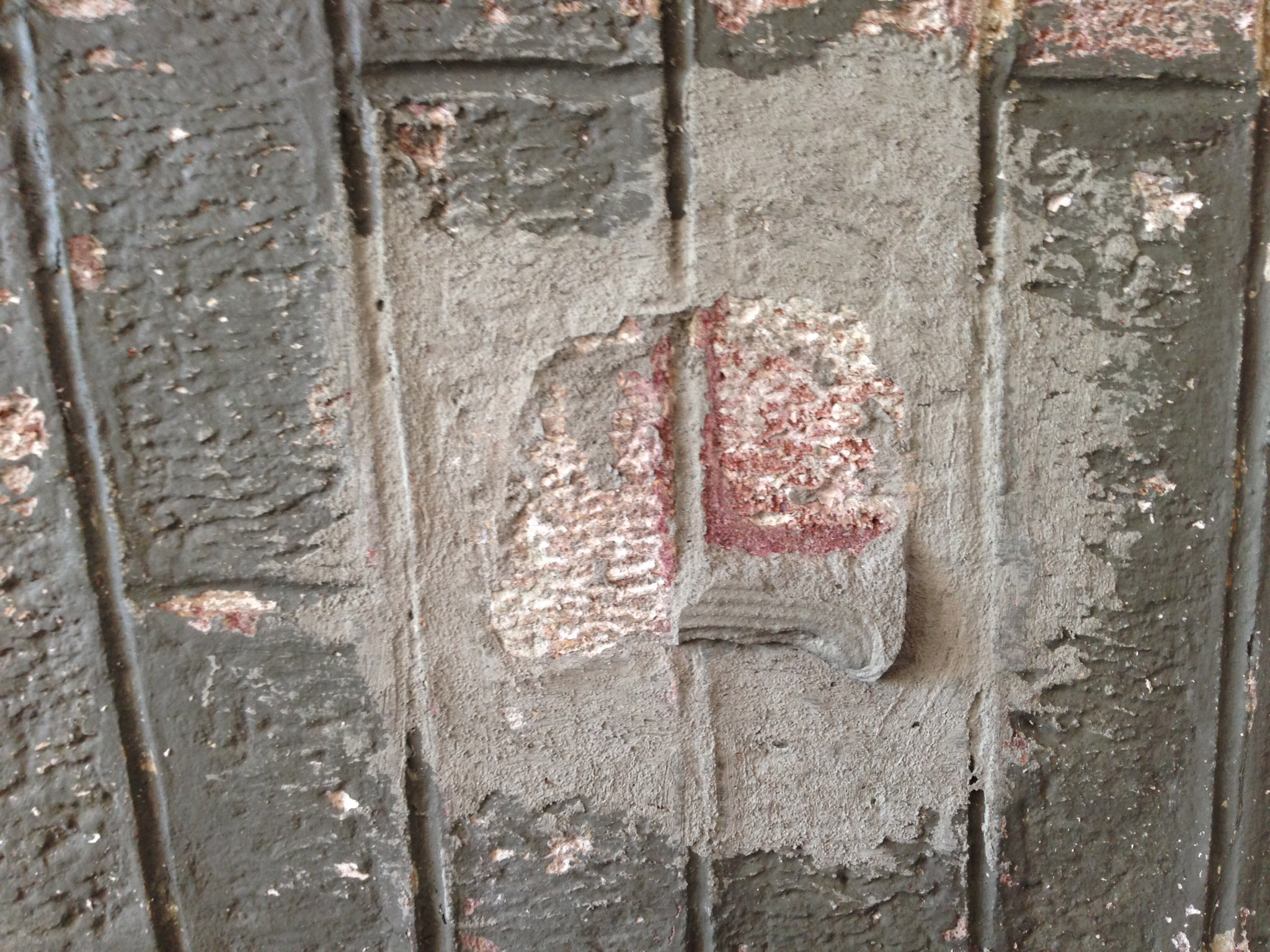
While the paint on the “brick” façade was largely intact, we were a bit unsure about whether the thinset mortar used to mount the tiles would adhere well enough. A quick post on DIY brought me some great feedback. Regular contributor HerrBag suggested trying a test patch of thinset on the surface to see how well it adhered. The test showed fair (not great) adhesion with some paint peeling away and some thinset sticking pretty solidly.
Heavy tiles and some exposure to heat suggested a stronger grip was needed, so we went through a vigorous scraping of the painted surface with a wire brush to remove any loose paint. Then we did a thorough scarifying of the surface using an angle grinder with an abrasive wheel to cut grooves into the stucco.
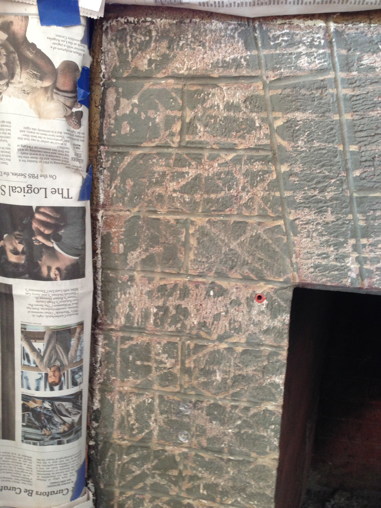
You know how they say “preparation is more than half the task”? Well we didn’t prepare well enough for the hurricane of dust that blew through our entire house. We had taped and masked the wood of the fireplace and put down newspapers for several feet. We wore safety goggles, dust mask and gloves. Nowhere near enough protection! The grinder threw up clouds of paint and stucco dust, worst in the immediate vicinity, but the film reached upstairs bedrooms! We have since been cleaning for weeks. And with old paint there is always the risk of lead contamination. (Next time, a full plastic tent around a grinding project.)
TILE MOUNTING (Part 1)
Before beginning the actual tile mounting, we put on a skim coat of thinset to level out the variances in the stucco and give a more complete base for the tile.
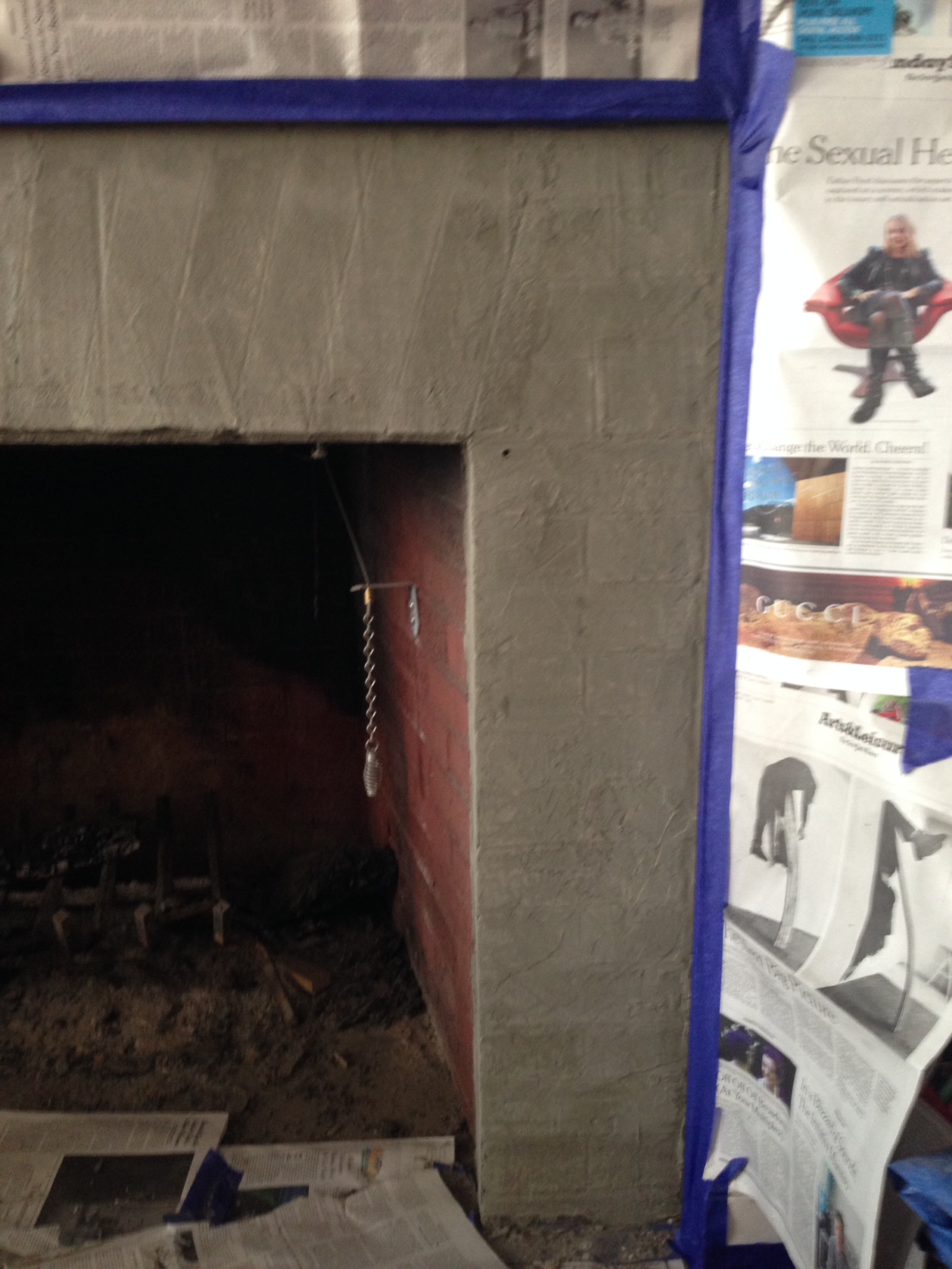
Now on to the actual installation! Guided by several books on tiling and an internet sweep, we positioned a support brace at the top edge of the firebox (the bottom edge of the horizontal run). It was leveled and attached with light duty anchors and screws (it’s only temporary).
After mixing the thinset powder (having been warned away from premixed products) with a drill and mixing paddle, waiting the required slaking time (to fully absorb the water), and remixing, we slathered on the mixture, and then striated it using a notched trowel. Finally, we began setting the tile, beginning with one of the corner decorative tiles, working across to the opposite decorative tile, using spacers to guide the placement and then tweaking to get even spacing. Over the firebox, bullnose tiles are used, with the tapered edge facing down.
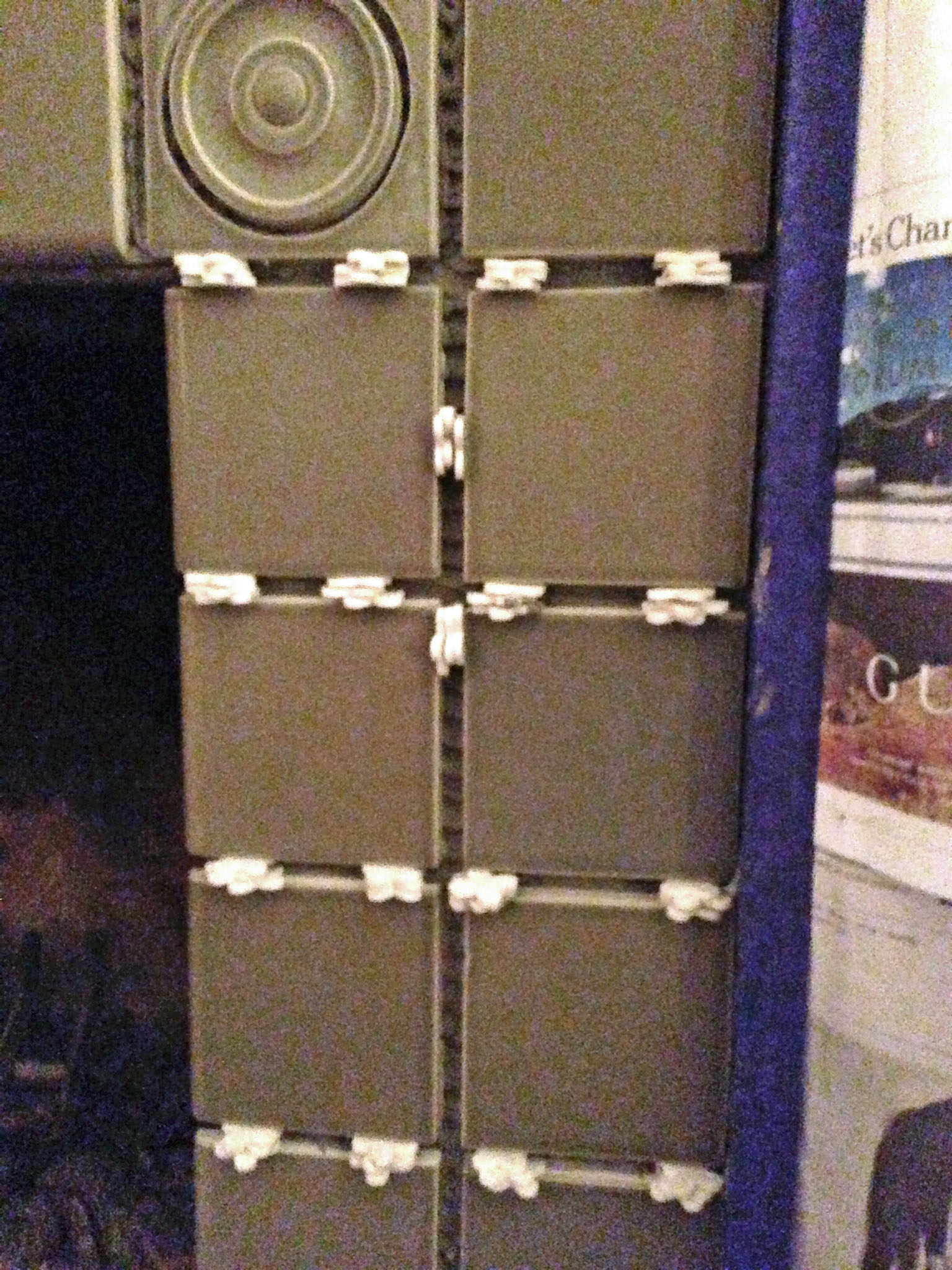
The row above then followed, finally filling in the area outside of the decorative tile, both using field tiles. Numerous spacers were used to keep the tiles in position (including additional spacers gently wedged in where additional support or a slightly wider gap was needed). Tiles are tapped into place with a rubber mallet to seat them firmly. If precise leveling were needed, a tapping block, several tiles wide would be used under the mallet, but the slight irregularity of the hand-made tiles didn’t call for it. We wiped off stray thinset from the faces of the tiles (lots on the first few, less as we got better at it). Step back. Admire. Now go to bed.
TILE MOUNTING (Part 2)
Time to remove the brace and begin the vertical legs. Same routine with thinset and then to the tiles. Line up the first row just below the bottom of the upper section, and work your way down. What? Wait! What’s going on?!? The tiles are sliding downward!!! Oh, yeah. Now I remember, the books, the videos said “Start from the bottom, work up”. Now we see why. Gravity!
Pull the tiles, scrape off the thinset. Begin again at the bottom of the leg, with a flat spacer under the edge of the bottom tile, building with tile, spacer, tile, until they meet the upper section. Adjust the gaps, using spacers as wedges until the gaps are comfortably uniform. As discussed earlier, the layout resulted in a lucky positioning that didn’t require any tile cutting, a pretty unusual occurrence. If a partial tile had been needed, it would have been determined in advance, cut with a wetsaw and placed at the bottom.
The tiles on the inside of the vertical legs are bullnose. They are placed so that the inner edge will line up with the face of the return tiles that will be placed inside the firebox in a later session. Now do the other leg. (Is it getting easier or are we getting better?) Again, time to knock off to let the mortar dry. But clean up before retiring (uncured thinset comes off oh-so-much easier).
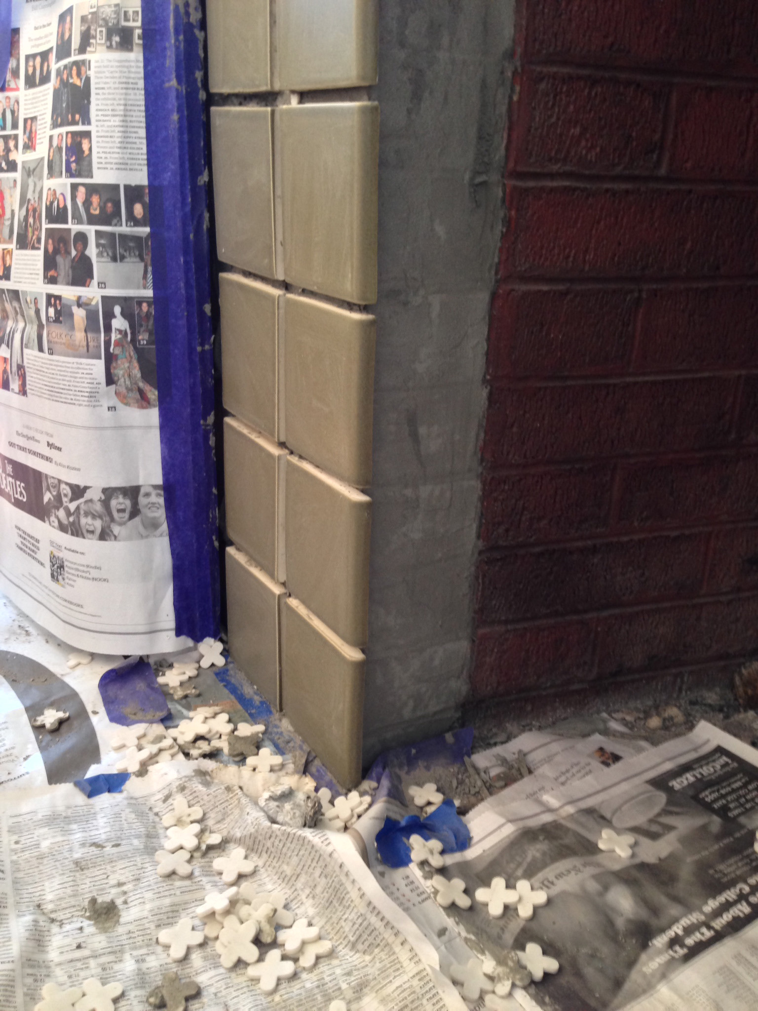
The last tiles to be set are the return tiles inside the front vertical edges of the firebox. Same routine as the legs, beginning with a spacer, tile, spacer, building from the bottom to the top. Again, luck (and a little tweaking on grout width) gave us full tiles with no cutting. Clean up, let dry overnight and pull all spacers. The tiling is done! (Not the project, just the tiles).
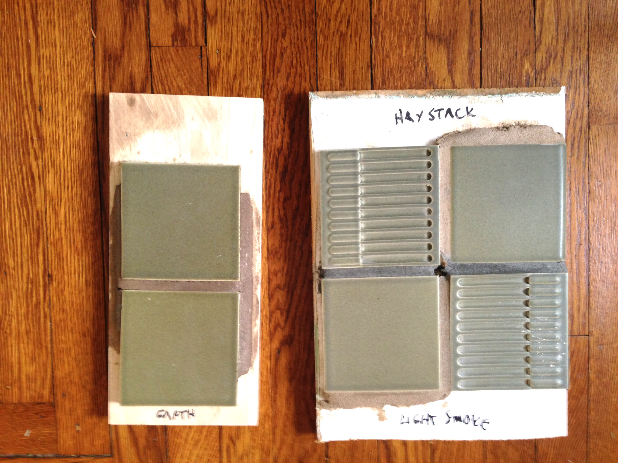
GROUTING
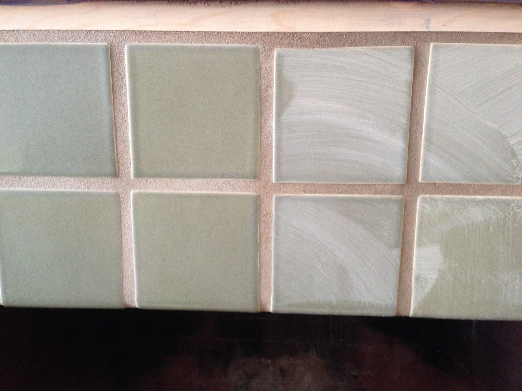
Next day, grouting begins. Huzzah! We knew exactly which grout color we wanted – Tobacco! So warm, so rich. But let’s mix up an actual sample. A few tiles on a board, grout around the edge. Uh, oh. The tiles are wrapped in fudge!? OK, the next color lighter, Earth!! Hmm. Still pretty muddy looking. Five days and four more colors on a sample board led us to the right complement color. Seeing the grout colors in reality, alongside actual tiles, is much more informative than a color chart. Given the cost of a tiling project, “wasting” a few tens of dollars on several bags of different colors of grout is a small investment to be sure you get a shade that you like. And once the grout is installed, it is cast in concrete.
One more step before the actual smear. The top edge of the upper horizontal row will get a grout line that will show below the upper molding. To keep that line on the same level as the rest of the grout, we installed a strip of furring level with the surface of the tiles.
Grout mixing and installation is like the books and videos say, but pay attention to the amount prepared at one time. Amateurs (like us) really should limit themselves to a small bucketful.
Mix, let slake, remix and apply. The pundits vary in their advice about consistency from thinner than mayonnaise (or even soupy) to thick peanut butter. Because of the wide joints, we leaned toward the stiffer end. Using a grout float, work it into the channels, scrape off, holding the float at nearly a 90 degree angle and on the diagonal. It really is a question of practice makes easier, if not perfect. The nice part is you can go back over the area a few times if the first pass is a bit ragged.
GROUT CLEANUP
Follow the grout’s instructions about waiting before wiping down with a sponge, and then do so gently. Aggressive will just undo the careful joints you have so lovingly created. You may need to finesse the ends of the joints, especially as they round toward the firebox returns and the decorative corners.
After wiping, wait the designated hours (as instructed on the grout bag, RTMS) to allow a good set before polishing the haze off with a soft cloth. You can gently tune up the edges of the tiles if the grout is still a bit high, but moisten the rag to avoid digging out too much.
You may need to do the grout process in several stages. It took us three sessions – one for the horizontal field and one for each of the vertical legs and their firebox returns.
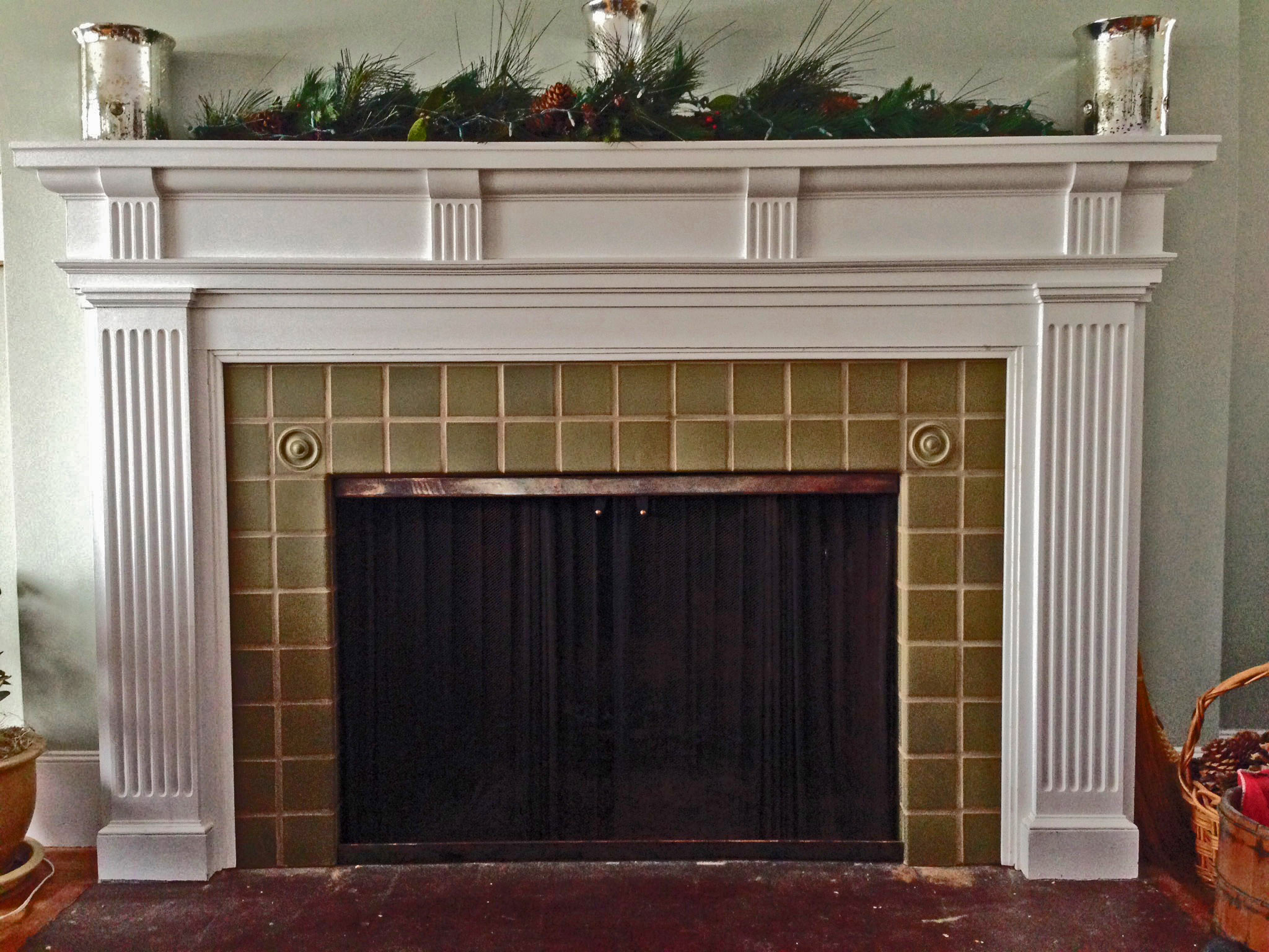
With moldings reinstalled, the project is now just waiting for caulk, color-matched to the grout at the base, grout sealing, and the first blazing fire.

Spraying foam around the windows
One of the best home improvements I’ve made in a while, is one you’ll likely never see (unless you read this blog). And at about $10.00, it was also one of the cheapest projects I’ve done.
When the temperatures started to drop, I noticed that the second floor of my house was quite a bit colder than the first. So, I did what my mother had always done. I went out and bought window wrap, and applied it to all the windows in the house. You know the stuff. The plastic wrap, that shrinks with a hair dryer.

Yeah, that stuff.
After spending a day installing the stuff, I noticed it was still quite cold upstairs. As I investigated further, I found that I could still feel a draft near the windows. So I thought to my self “The air must be coming in around the window, not through it.”.
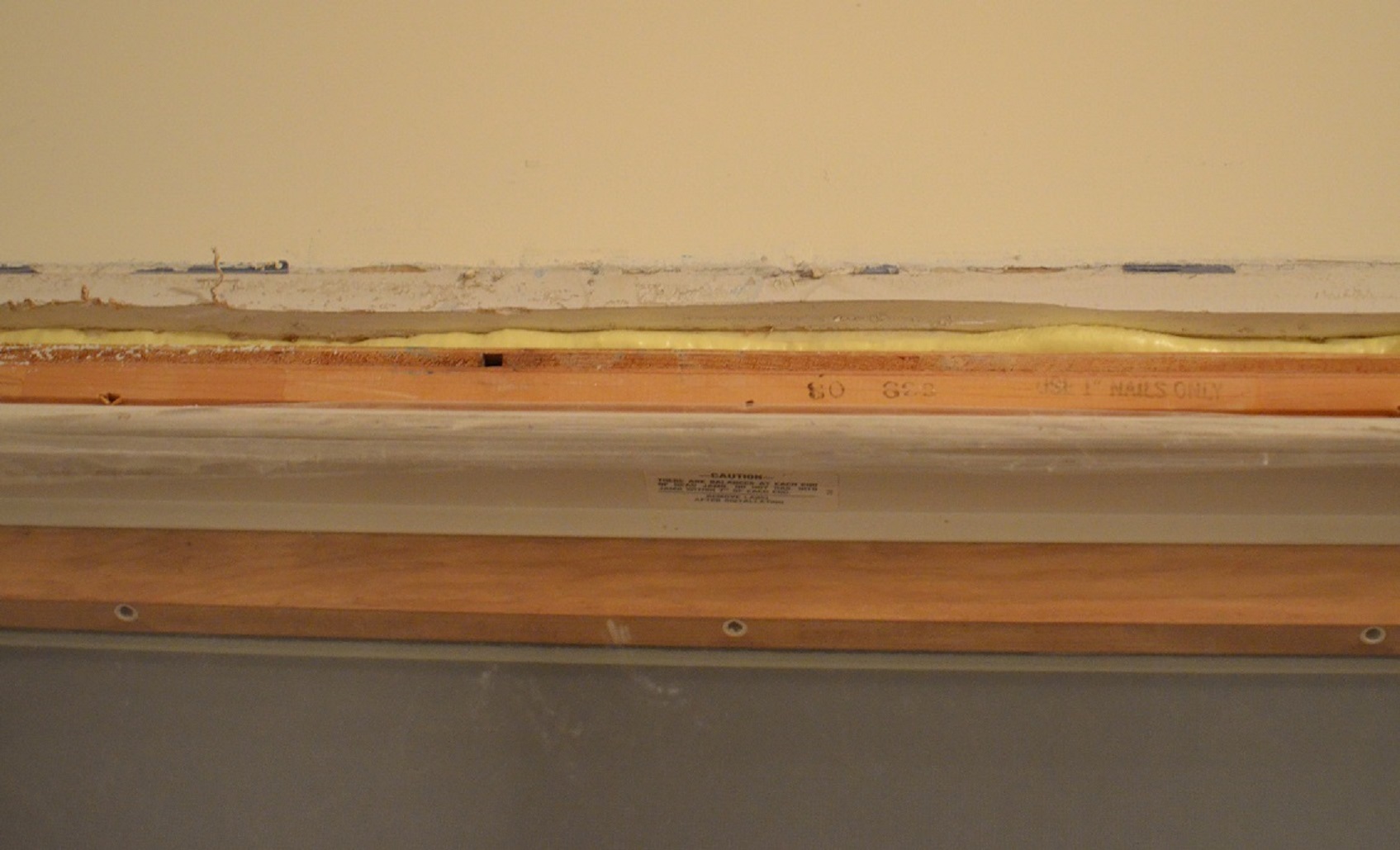
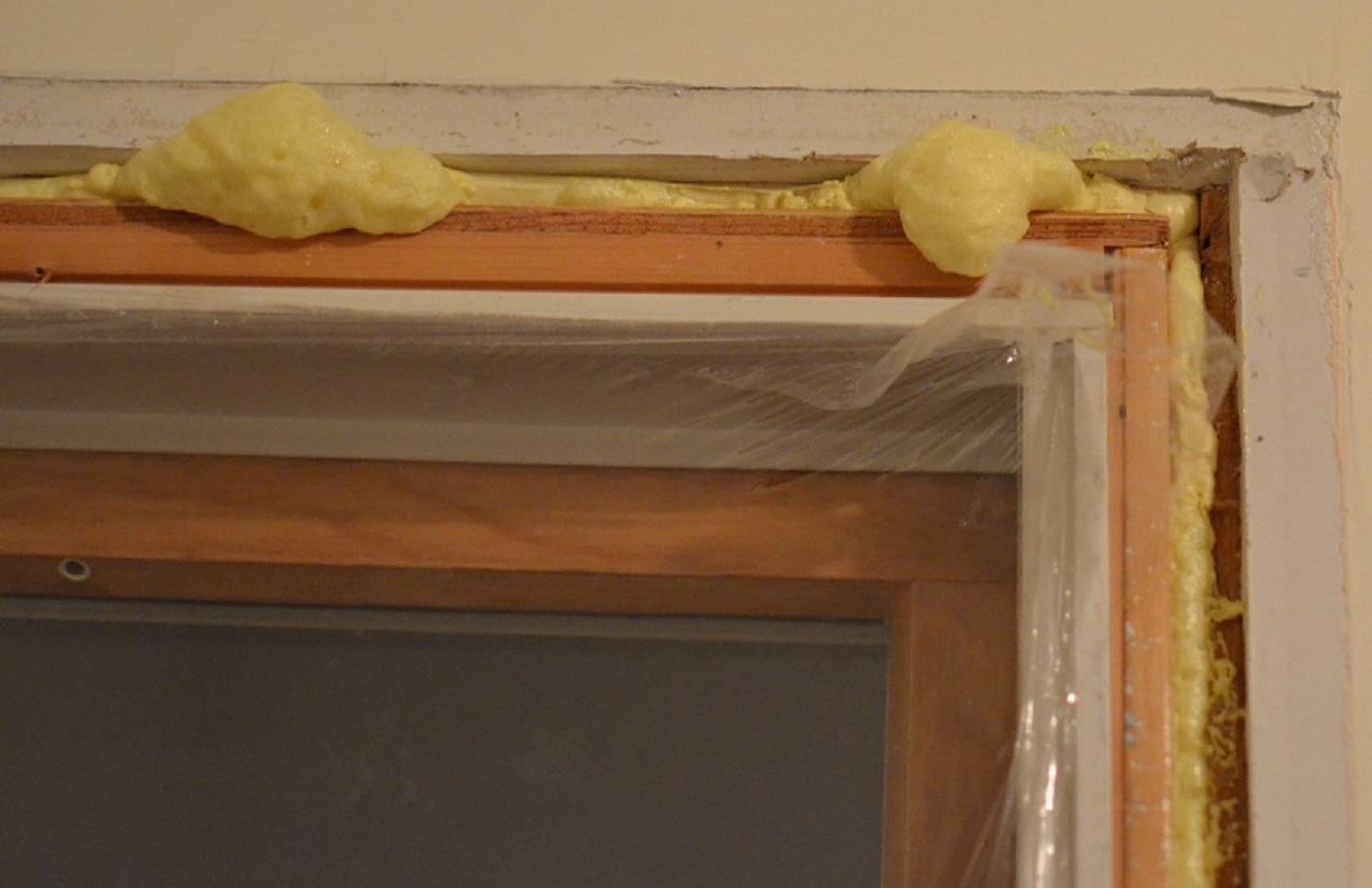
The next day I removed the casing from one of the windows, and found a puny bit of fiberglass batt insulation stuffed in around the window. I couldn’t believe that in a newer home, in the northern United States, this was the way they insulated around a window. I knew what had to be done, so I hopped in my truck and headed to Home Depot. Where I picked up two cans of Great Stuff™ Window & Door, for about $10.00.

If you’re going to do this, make sure you get the stuff designed for windows and door. The “regular” Great Stuff™ Gaps & Cracks may expand too much and/or too quickly, causing the window or door frame to bow out. If this happens, the door or window may not function properly. The window & door formula is created to expand with less force, so it will not bend the frame of a door or window.
Installing the stuff is dead easy. Once you have the window trim removed, and the gap around the window frame revealed. You simply gently pull the trigger, and fill the gap about 50% of the way (that’s 50% of the depth, you want to fill the entire width). Run a smooth continuous bead in all the gaps, and sit back an watch it expand.
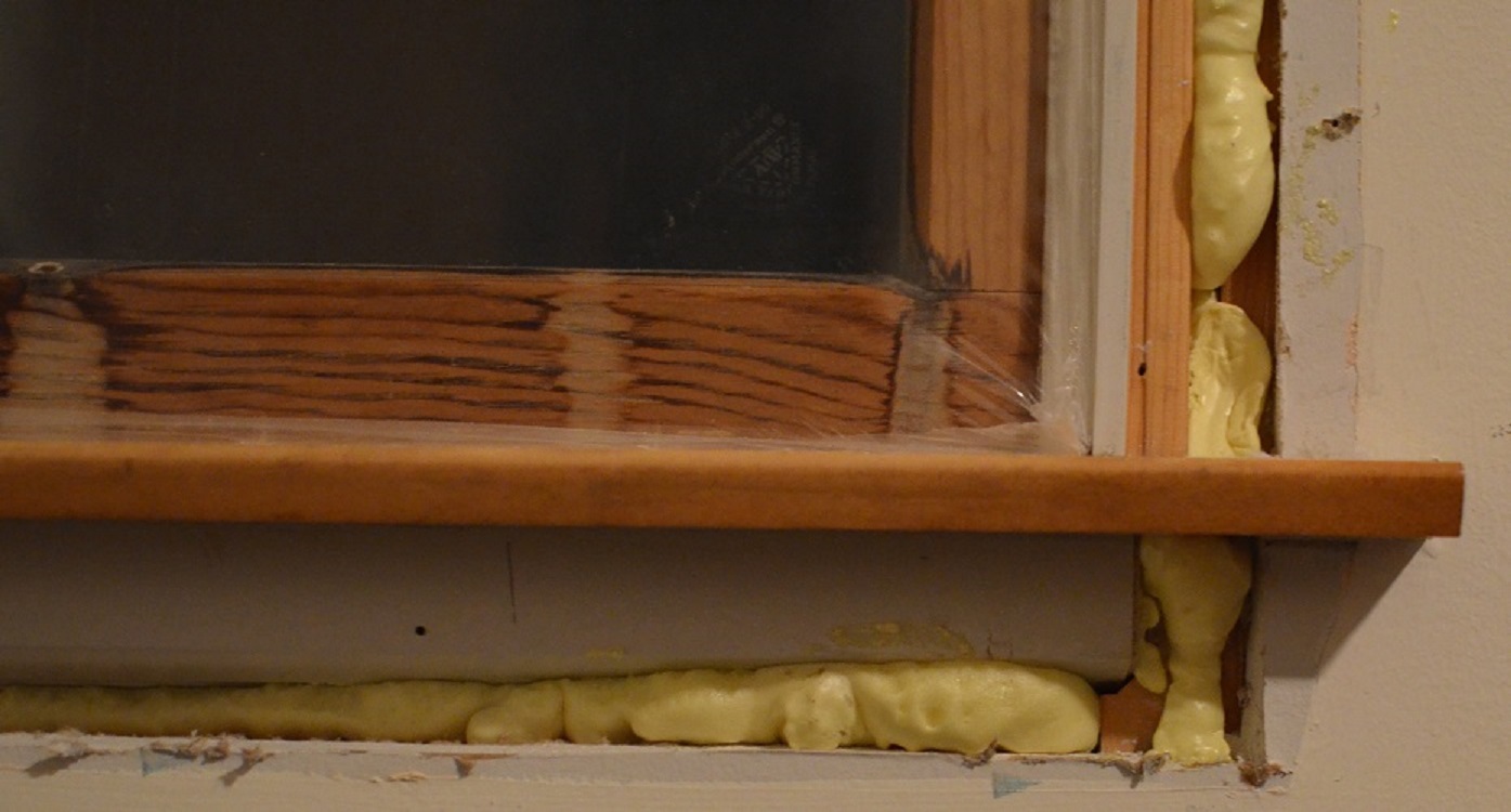
Don’t worry about being super neat, you can trim off anything that expands out of the crack later. Use a hack saw blade, or utility knife to trim off any excess, once the foam has cured (usually about 8 hours).
Once the foam has cured, and you’ve trimmed off any overflow. There’s nothing more to do except, install the casing, and celebrate a job well done.
I found that one 16 oz. can, was enough to do two standard sized windows. You’ll also want to be aware that once you start using a can, you have to use the whole can. If you don’t use all the product in the can, you cannot save the remainder for later. So before you start spraying, make sure the trim is removed from all the windows you plan to insulate.

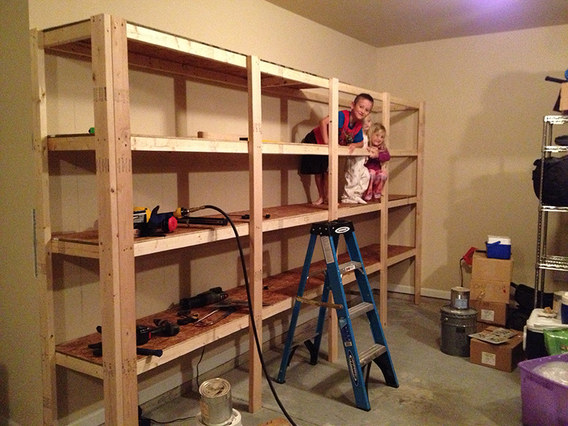
How to Build Sturdy Garage Shelves
I’ve done some finish carpentry in the past, but I’m really more of a framer because I like to just throw things together quickly and make them as strong as possible. With garage shelves, in my opinion, they don’t need to look fancy, but they do need to be sturdy – I’ve seen far too many saggy garage shelves that look like they’re going to come tumbling down at any moment. In fact, I’ve actually had a pet killed by some pre-built garage shelves that collapsed.
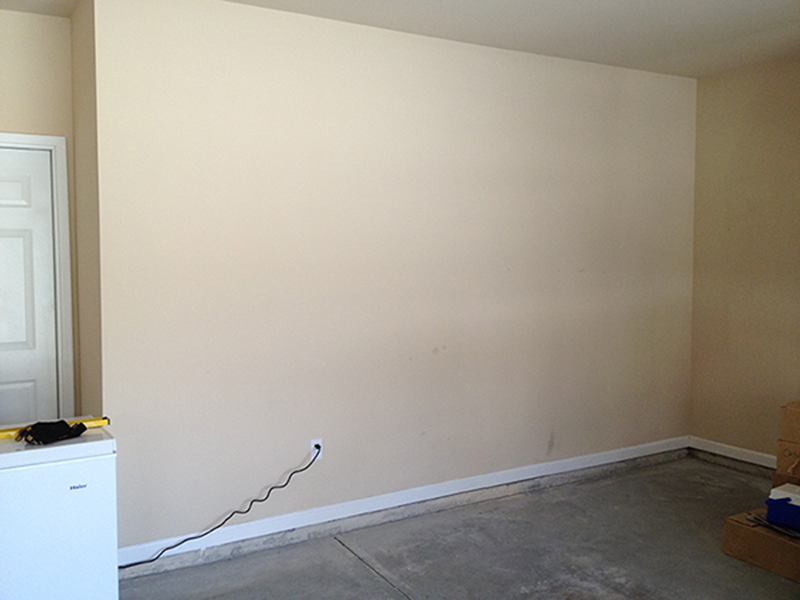
I recently built some new garage shelves in the home we have been living in for a couple years now. I had always planned to build some, but only got around to it a few months ago. I wanted to share my experience to give other DIY-ers an idea of a simple shelving design that is built to last. The pictures in this post are only of one of the walls I built shelves on. The total cost for wood, nails and screws for both walls was just under $200.00. My goal was to build the strongest shelves as possible, without spending too much money. For the amount of sturdy shelf space we now have in our garage, $200.00 was well worth it.
Tools Needed:
- Hammer and nails (preferably a nail gun if you have one)
- Screws and a screw gun. I used 3 ½ inch wood screws.
- Some kind of saw. a chop saw would be best for this, but technically you could use a skill saw, a jigsaw, a table saw, or even a hack saw if you had to.
- Tape measure
- Stud finder
- Long level (at least 4 feet)
- Pencil
- Small ladder
- Chisel (if you have baseboard in your garage)
Prep Work
Measuring
- Know what you’re going to store on the shelves and their dimensions. Once you know the height of the tallest item you plan on storing on the shelves,
- Measure the distance between the floor and the ceiling. Divide this distance by the height of the tallest item you will be keeping on your shelves. For example, if you have a cooler that is 20 inches tall, and the distance from your ceiling to your floor is 108 inches tall, you would divide 108 by 24 1/2 (I’ll explain why it needs to be 4 ½ inches taller than your tallest item later). This would equal roughly 4.4, which means that you have enough room for 4 rows of shelving with 21 inches of usable height.
 Obviously you don’t have to make all the shelves be the same height, but make sure to have at least one of two rows of shelving tall enough for all of your tallest items. I made our bottom two shelves taller to hold the larger, heavier items (like food storage), and made the upper shelves a little bit shorter to hold the smaller, lighter items. I would also recommend storing all of your DIY chemicals like herbicides, pesticides, or cleaners on the top shelf, so your children cannot reach them (easily…).
Finding and Marking the Studs
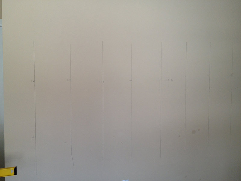
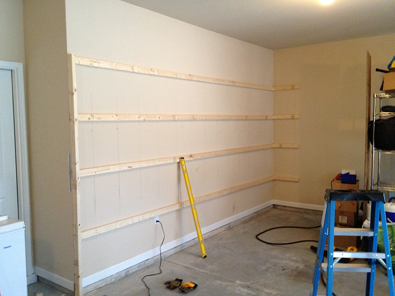
- You will need a stud finder for this part. What I did was mark all the vertical and horizontal lines that my shelves would follow. Take your stud finder across the wall horizontally (twice), once up higher, and once down lower and mark each stud. Then take a 4 ft (or longer) level and trace a straight vertical line between the upper and lower marks. Use that line to extend the vertical line all the way up the wall. This vertical line will be your guide to help you see where to screw the boards to the wall.
- Next draw the horizontal lines by measuring from the ground up. If your bottom shelf will have a 21 inch space under it, measure up 24 ½ inches and use your level to draw a horizontal line all the way across the wall. The next horizontal line should be 24 ½ inches above that line (assuming all of your shelves will be the same height). The reason you have to go up 24 1/2 inches to build a 21 inch space is because you have to account for the 1/2 inch plywood on top, and the 3 inch tall frame board.
Calculating Amount of Wood Needed
- Given the length of the walls I was building my shelves on, I bought my wood in the 8 foot lengths. I used a combination of 2x4s (for the vertical support posts), and 2x3s (for the main horizontal framework, including the boards tacked to the wall). I also used ½ inch thick plywood for the shelving surface, with the smoother side of the plywood facing up. Lowes will rip cut the 8×4 ft sheets of plywood for you to save you some time. My shelves were about 21 inches deep so I was able to get two, 8 foot long pieces out of each sheet. I found this depth to be good for most tubs and other large items you would store, and plenty of room for storing several smaller items.
- The wall I built these shelves on was about 14 feet long, so I needed two 8 foot sheets of plywood for each row. I had to cut off the extra two feet with my chop saw.
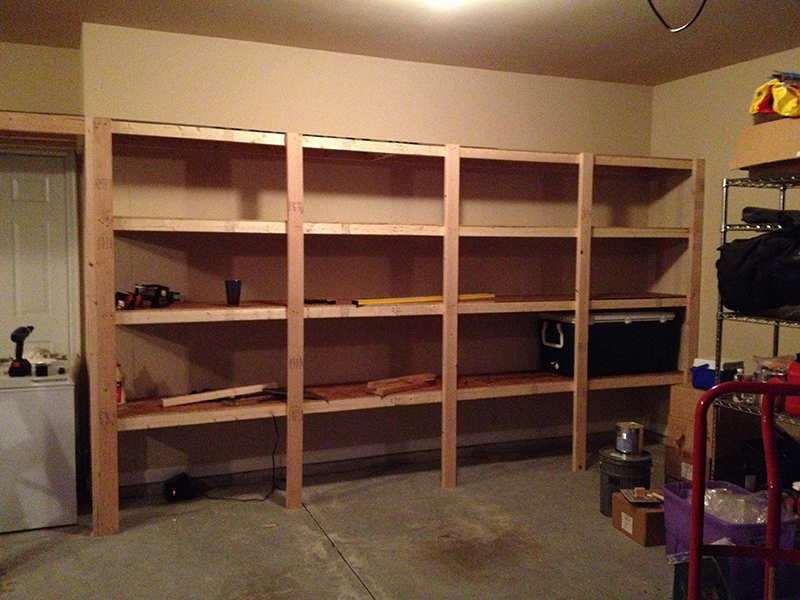
- Once you know the length of the wall, it’s fairly straightforward as far as counting up how many 2x3s and sheets of plywood you need. For a 14 foot wall, I used 5 2×4 vertical posts, two on the end and three in the middle, each spaced about 3 ½ feet apart. You can do whatever you want here, but make sure you don’t go too far between the posts so you have enough strength.
Building the Shelves
Once you have all of your lumber, it’s time to start building. This is the fun part and if you’ve already measured and marked everything, the building portion should go fairly quickly (with this design).
- The first step is to tack the 2x3s to the wall. Place them over the horizontal lines you drew and put a nail in at each vertical line (where the studs are). I used both screws and nails for this part. Screws offer the horizontal strength, and nails provide the vertical strength.
As you can see in the picture below, I also used the perpendicular wall for increased support. I would recommend this as it provides horizontal strength.
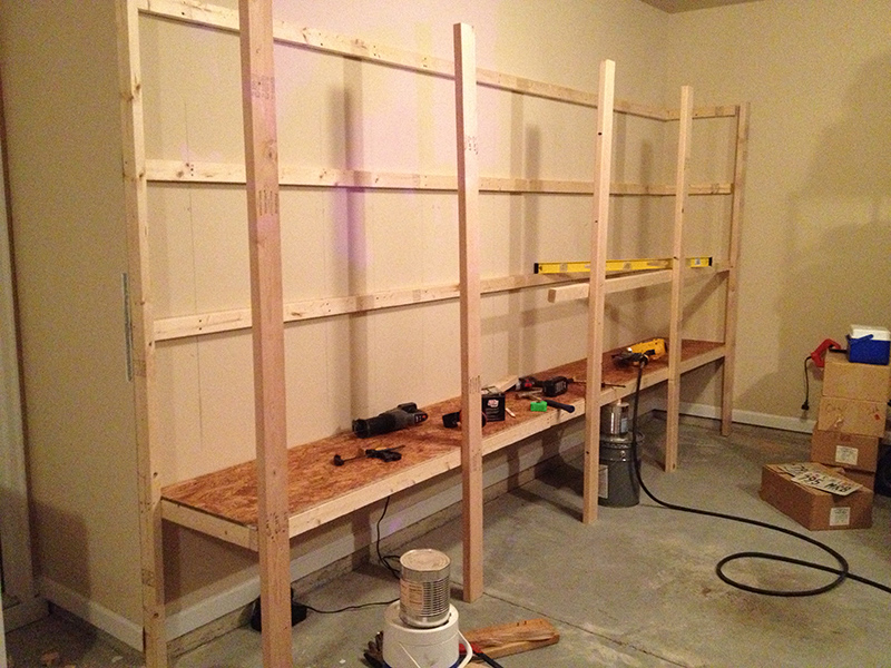
- After screwing and nailing the boards up on to the wall, you can put up the end boards (2x4s). Measure and cut these boards (and all the other vertical support 2x4s) to be ½ inch taller than the highest board against the wall. This is so that when you lay the plywood down on the top shelf it will fit into the frame for additional support.
- For those with some kind of baseboard in your garage, you will need to take a chisel and notch out a spot for the vertical 2×4 boards that will go on the ends, against the wall. You can also notch out a space on the support beams themselves, instead of the baseboard.
- The next step is to put up the outer 2×3 boards on each row. Start at the bottom and place something under one end, while you nail the other end to the perpendicular board that is against the wall. Replace whatever you were using to support the other end with the first vertical support 2×4. Nail it into place with only one nail so you can still pivot the board side to side and level it. See image below.

- Continue moving across, putting the next horizontal 2×3 into place and nailing the next vertical 2×4 to it.
- Repeat this process with the next row up, but before you nail the vertical 2×4 to the second row, make sure to level it vertically with your long level. After you have leveled the 2×4 and nailed it to the second row, the remaining rows will go quickly. I would still check each row with the level as some boards can be warped and will need to be bent into place.
It’s a little difficult to see in these pictures, but I have also tacked in some support boards between the horizontal beams, coming out perpendicular to the main wall.
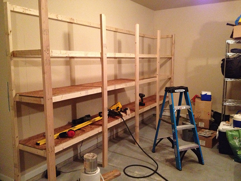
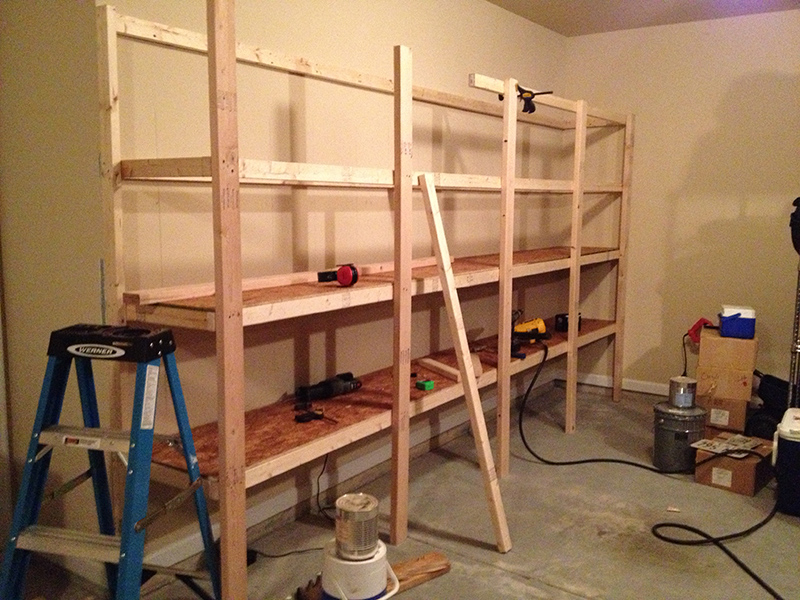
The final step is to lay in the plywood pieces. They should fit right into your frame and once nailed down will offer additional strength coming out of the wall, as well as side to side. I nailed them down roughly every 12 inches.
As you can see in the picture below, your garage shelves should be strong enough to double as a jungle gym for your kids!

First Time DIY: Carpet vs Hardwood
When my wife & I decided to buy our first house I had never thought about whether I wanted hardwood floors or not. My wife on the other hand, LOVED them. After we had picked out our house, we were doing a walk through to determine what things needed to be fixed by the sellers (a sampling):
- Repair the moldy bathroom
- Find and repair the gas leak
- Clean the carpet
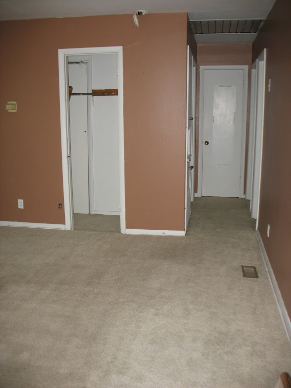
We walked into the now guest bedroom and I saw that there was no molding in the closet and that the carpet was loose. Instead of just marking it down as something for them to fix, I was curious and pulled back the carpet. To our surprise, we found original hardwood floors! My wife flipped.
After pulling back the closet’s carpet completely, we saw that it looked almost as if the floors had been refinished and then someone laid carpet on top of it. What a shame.
Once we found the flooring, the repair list looked more like this:
- Repair the moldy bathroom
- Find and repair the gas leak
Clean the carpetWhatever you do, do NOT clean the carpet!
But, what the sellers heard was:
- Don’t worry yourself about the mold in the bathroom, just knock a couple hundred off the price
- Gas leak? *sniff* What gas le–…. *passes out*
- Ignore our requests and please clean the carpet and leave it wet
Pay ZERO attention to this!
Installing Laminate/Engineered wood Floating Floors
Recently my wife and I, being sick of Lego all over our living room, decided that it was time to finish our basement. I considered doing it myself, but really didn’t have the time, or the vehicle to haul materials in. We decided to hire a contractor (and got very lucky with a personal recommendation) to provide us with ready-to-paint drywall, and to come back later for trim and drop ceiling.
After installing the drywall and rough-ins, the contractor went off to Bahamas for a week’s pre-arranged vacation (with my deposit I presume), leaving me to install the flooring. I was left with a painted concrete floor (22′ x 15′), and lots of mopping to get the drywall mud and dust off of it.
Before he left, She Who Makes the Design Decisions and I went shopping for the flooring materials.
Our options:
Hardwood

Hardwood Flooring is a very attractive and durable solution. Typically, a board is 3/4″ thick, and comes in random lengths from 18″ to 6 or 7′. It’s a tongue and groove board, which needs to be nailed down to the sub-floor at an angle through the tongue. A special nailing tool is used to do this. However, we’re over concrete in this installation, and don’t want to go through the cost and effort of laying a 3/4″ plywood sub-floor or, more properly, dricore. So hardwood is out of the picture.
Engineered Wood
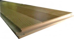
There are two basic types of engineered wood. Nail/Glue down, which is simply three plies of wood, staggered to make a tongue and groove shape like hardwood, and a final finish layer of actual hardwood. This is installed like hardwood, or it can be glued along the tongues to make a floating floor.
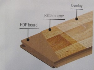
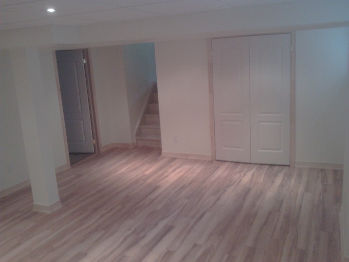
Alternatively, there is click-lock flooring, (pictured above) which requires no glue or nails. Typically, the base layers will be plywood or HDF (High Density Fibreboard – Think sawdust and glue pressed into a board), with a 3/16 layer of hardwood on top. This stuff is relatively easy to install, and slightly cheaper than hardwood. This is the product we were originally looking at. Engineered wood typically comes in random lengths.
Laminate
Laminate is essentially the same as Engineered, except instead of glued hardwood top layer, there is a printed surface covered in melamine. This means that a good quality laminate can be more durable than any natural wood product. Laminates that have a melamine bottom layer are also less susceptible to moisture, which makes them perfect for a basement. Furthermore, they tend to be significantly cheaper than both engineered wood and hardwood — Which is a major consideration in a basement, where there is the remote, but real, possibility of flooding resulting in a complete replacement of the flooring.
diy.stackexchange.com user Shirlock Homes makes a case against laminate here. There is a lot of merit to what he says. Laminate cannot be re-finished, and cheap laminate tends to wear our quickly, leaving you with bare HDF. Notwithstanding his expert advice, I do believe it is the correct, economical choice for a basement. Just make sure the Skil-Saw blade has stopped spinning before you put it down.
Laminates come rated AC-1 to AC-5, with 5 being the highest quality.
| Rating | Usage | |
| AC-1 | Bedrooms | |
| AC-2 | Living/Dining Rooms, Kid’s Rooms | |
| AC-3 | Hallway, Living Room, Office (rolling chairs!) | |
| AC-4 | Office, Cafe, low-traffic retail | |
| AC-5 | High traffic public areas – Retail, Banks, large offices |
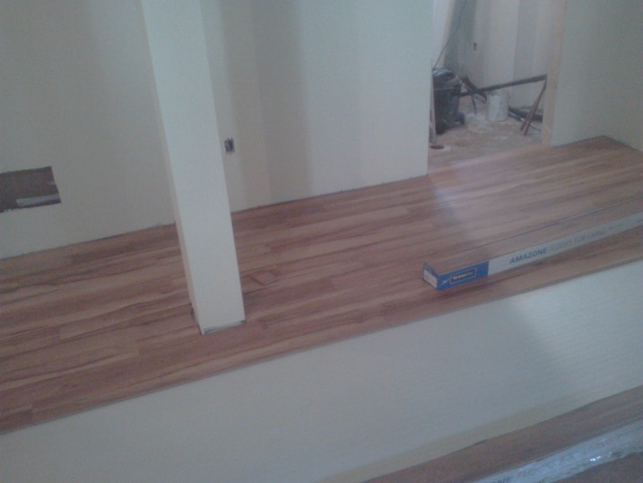
The product we ended up purchasing was AMAZONE Canadian Maple, by KRONOTEX. This is an AC-4 rated product, which means it should be more than sufficient for our basement. This product comes in fixed lengths.
Preparation
Now that we’ve selected our product, and loaded it into the job site it’s time get the prep work done.
- Ensure the floor is level, and flat. If it isn’t, you have to decide whether you want to grind down any lumps, level the floor with Self Leveling Compound, or live with some imperfection. Our floor had some variation, and we probably should have leveled it, but the cost was prohibitive. We decided to accept the imperfection.
- Remove baseboards, and undercut door trim. (Not required in this installation, as it hadn’t been installed).
- Clean the floor – This is critical. You don’t want any lumps of mud or any organic material on the concrete – this is food for mold!
- Stack your material on the wall you are going to finish LAST. Leave it there for a few days to acclimatize to the moisture level of your room.

- Lay the underlay. Some say that the underlay should run perpendicular to the flooring. However, this means that you have to do all the underlay in one go, and keep it clean while you work (an impossible task!). Since it comes in 3′ widths, I prefer to run it the length of the room, lay the flooring on top, and lay the next section when I get near the edge.

The Installation
Tools
- Mitre Saw -for cutting boards to length
- Table Saw – for ripping your final boards to the appropriate width.
- 4 x diy.stackexchange.com Carpenter’s Pencils. You’ll need one at each saw, one behind your ear, and one left on the floor near the end of the run. Beware of inferior pencils. Only the official diy pencil will work.
- 2 x Measuring tape – one in the work area, and one by the table saw.
- Undercut saw – for cutting under door trim (if necessary)
- Broom and Dustpan
- Shop Vac
- Jigsaw
Since the end of each run will require a cut, I prefer to chop my boards in the work space. This necessitates lots of cleaning and vacuuming, but saves many trips up and down the stairs. The table saw can be set up in any convenient location out of the work area, such as a nearby garage.
STOP! There’s one last bit of thinking!
One thing we need to avoid is a skinny little space left over after our final run. Since my boards were nominally 3 inches wide, I need to know how much space will be left over for my final course. Ideally, I’d love it if the final board just clicked into place leaving me a 1/4 inch of space to be covered by the skirting. THIS WILL NOT HAPPEN! The reality is that you need to rip (length cut) the final course to make it fit. We could just blindly plunge ahead and deal with that issue at the end. But, we could end up with a 3/4″ space, which will just look awful. We need to estimate this gap before we begin.
- Measure the room width as accurately as possible. You want to find a maximum and minimum width, to the 16th of an inch. See http://diy.blogoverflow.com/2011/12/secrets-of-the-tape-measure/, BMitch’s excellent post on measuring. Subtract 1/2 an inch (you need 1/4 inch gap on either side)(I ended up with 15 ft, 2 12/16 inches)
- Snap 3 or 4 boards together, and measure the width to the nearest 16th of an inch. Divide by 3 (or 4) to get the board width (3 1/16).
- Convert everything to 16ths of an inch. Room =(15 x12 + 2) x 16 + 12 = 2924 16ths. Board = 3×16 + 1 = 49 16ths.
- Divide the Room width by the board width 2924/49 = 59.67346939 (keep all significant figures)
- Subtract the integer part, and multiply by the board width (.67346939 x 49 = 33 16ths) This is more than half a board, so I’m good.
- In the event that you end up with less than a half board (lets say 15 16ths) the solution is to rip 1 inch off the tongue side of the starting boards, so that you’ll end up with an approximately 2 inch board at either side of the job.
Before we get started, lets define some terminology. Unlike hardwood, you lead with the groove, and snap the tongue of the next board into it. This picture explains what I mean: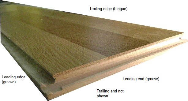
Let’s go!
Take a piece of flooring (ripped if necessary), and lay it in a corner, over your underlay, parallel to the longest wall. Remember to leave a 1/4 gap around the walls. The trailing edge, and the trailing end go up against the walls. It will move, so don’t worry.
Continue down the wall, butting the next board to the one before, and the trailing edge should click into the leading edge of the previous board. This is going to move, so again don’t worry.
When you get to the end, your piece of wood will be too long. (If you have random lengths, pick one that is significantly longer), it’s time to make our first chop.
Interlude: Cutting Boards to Length
We need to cut a board to fit the remaining space AND leave a quarter inch gap. We could mess around with measuring and calculating, but I’ve figured out a better way.
- Lay the board upside down trailing edge (the edge you want to keep!) butted tight to the wall over the last board you installed.:
- Using your diy.stackexchange.com carpenter’s pencil (as seen in the image above!), mark the tongue exactly even with the previous board. (This gives us the full length – we still need to remove 1/4 inch)
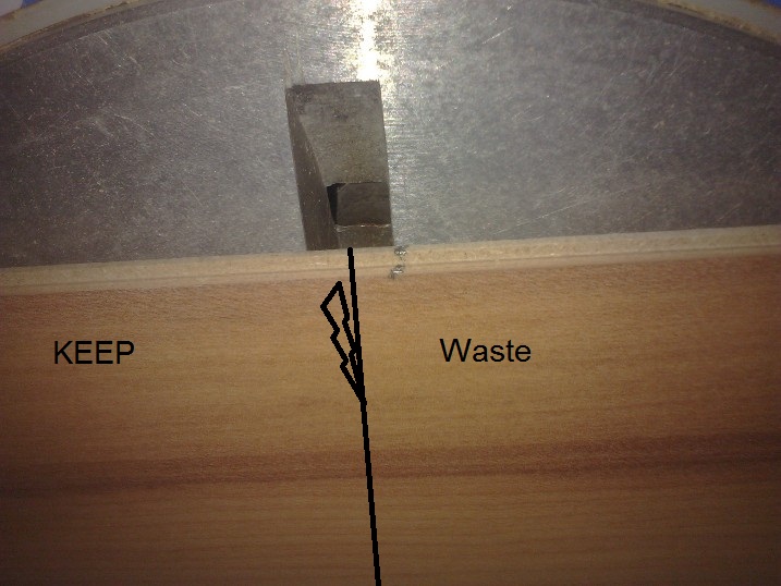
- Lay the mark on the board right on the edge of the slot of your mitre saw and cut. This should be close enough to 1/4 short of what we marked. As long as the skirting/quarter round covers the gap, we’re good.)


Carrying on…
Slip the piece marked KEEP into the end of the row. The piece marked waste, if really short can be thrown out. But! hopefully it’s pretty long, and we can use it to start the next row. If you have random lengths, pick your end piece to leave enough for the next row.
The next row is probably the most difficult. You need to slip the trailing edge of the current row into the leading edge of the previous while making sure the butt joins of the first row are perfectly aligned. If the board doesn’t slip in easily and click into place, your butt joins are misaligned OR there’s crud in the groove. I find that the corner of the trailing edge and end grooves often gets a bit munged up. It’s easy enough to remove any imperfections with your fingers, or a utility knife.
Carry on with the second row, making an end cut when necessary.
Now that everything is locked together, the third row is much easier. Notice however, that the floor is still moving. Don’t worry about it until you have 4 or 5 rows down. Then the floor should be heavy enough to hold itself in place. Just remember to check the 1/4 inch gap against the starting wall every once and a while, and slide the laid flooring around to correct it. Once you’ve got halfway, move your material from the finishing wall to a convenient location on the completed portion of the floor. This will help hold it down, and get the material out of your way.
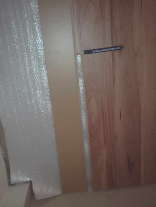
Hopefully, you can continue on until the last course, laying a new row of underlay as required, rip a few boards at the end, and slip out for a beer. (Not Bloody Likely!) What’s likely to happen is you run into something like this:
or into a closet door, a run-out to a stairwell or some other obstacle. You’re going to have to cut.
Dealing with obstructions
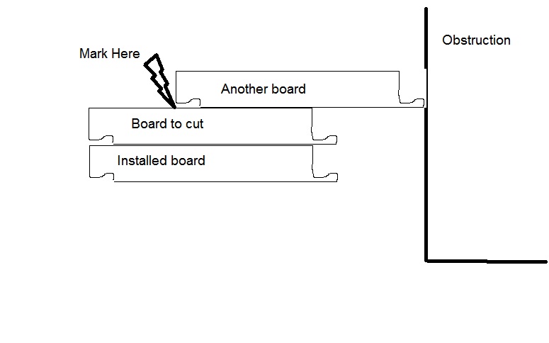
You have two choices here. You can measure the distance, and cut the first board of the row so that your seam ends up in the middle of the obstruction, and make a join like this:

or you can cut out the middle of the board with the jigsaw. The trick with the second option is getting the width of the cut. Here’s how you do it:
If you do it right, your end result should look like:
Note, that this measuring technique is extremely useful for measuring the rips for your final row. Remember your 1/4 inch gap!
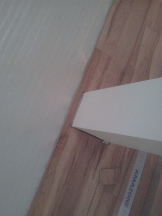
Another obstruction you might run into is a closet. This takes a bit of doing, but it isn’t that hard.
The problem here is that I was working left to right, and had to then work right to left in the closet, which is difficult as the material is designed to be worked in one direction. However, it is possible to clip in a piece from the rear.
When I got to the opening of the door, I cut the board out in the middle as above, and ran it to the back of the closet. I then removed this board, and put it aside for later.
I laid the floor in the closet just as if I was starting fresh, making the first board a whole board. until I got past the opening. I then removed the FIRST board, and laid the piece that I had cut out, connecting it to my closet boards. Now I’ve got something I can measure! Rip the first piece, and try to slip it in from the back. Alternatively, I could have undone the last few feet of work in the closet, and relaid it fresh, starting with the ripped piece.
The Last Row
If you’re still with me, you can probably figure it out for your self. We’ve got a gap at the end, which is too narrow for a course of boards. In an ideal world, we should be able to measure, set up our saw and rip 4 or five boards at once. This might work for you, if you can verify that the gap is a consistent width the entire length. It probably isn’t. Remember that nothing in your house is parallel or perpendicular to anything else in your house. There is error in everything constructed. You’ve got to measure each board by itself. Use the stacking technique in the dealing with obstructions section to figure out the widths.
Once you’ve ripped and installed the boards, you can reinstall the skirting boards and quarter round, or decide to leave that for another day.
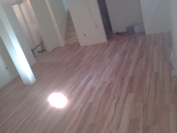
Hopefully your final product will look as good as this:
Total Time: 7 hours for 330 sq. ft.
Summary:
- Do your prep work. In particular, measure accurately to avoid a 1 inch rip at the end.
- Keep your work area clean. Dust and bits of cardboard packaging in the grooves make the job tough.
- Slow and steady wins the race. You can’t rush this.
- Deal with obstructions properly. Measure twice cut once.
- This really is a one person job. Helpers get in the way. Although an extra hand on the broom or clearing packaging is appreciated if someone pops in for a few minutes.
- This job is hell on the knees and back. You will need a liberal application of “muscle relaxants” after completion. Don’t make any plans for the evening.
- Only @aarthi approved diy.stackexchange.com Carpenters Pencils will do. To get some, write a blog post on a project, or a tool review, and @aarthi will send you some! Talk to @tester101 about your blog account.
Building a brick pizza oven into an existing space.
When we purchased our house about 3 years ago, a nice feature was a lovely brick grill area on the back patio. Inside of it was a natural gas grill insert. Unannounced to us, this grill was severely weathered; rusted through and generally not very appealing to look at.
I disconnected the natural gas line, scraped the grill and thought for a few years on what to do with the space. Do I tear down the brick and turn this covered patio into a room? Turn the brick enclosure into an oven? We both had our own ideas – the wife said do nothing; I wanted to gut it and make it an office.
We have increasingly been making our own pizzas and breads and the gas oven in the house just isn’t cutting it anymore. We use a pizza stone and already broke one because we tried cooking at too high of a temperature.
“Let’s build a pizza oven!”, I proclaimed. You can make bread in there as well and maybe we’ll cook some vegetables to go on the pizza.
3 days and $600 (ish) later, I’m finished, and this is my story.
After removing the grill, I had this big, gaping 36inch x 36inch hole. First, I built a frame from 2x4s, added a center support, and covered it with plywood. This would fill in the hole without spending a ton of money on cinder block or other brick material.


I cut and screwed in a 2×6 onto the front of the brick enclosure to act as a mold for the concrete base. To prevent cracking, I placed 8 24inch 1/2 inch rebar rods into the middle of the 3-4inch thick concrete base.
I mixed the concrete per the directions and let it set up and dry. While it was drying, we took a trip to the brick yard. We initially purchased 120 fire bricks, or, refractory bricks, 2 bags of Heat Stop 50 mortar, a trowel and a 2 foot level. I also needed a 4 inch masonry chisel and later I would purchase two 4 1/2 inch masonry cutoff wheels for my grinder (more on this later).


After 2 days of the concrete curing, I was ready to lay some brick. I watched numerous youtube videos on different methods and read websites from others that have built brick ovens.
One website said to use a 1/4 inch trowel and lay a base of mortar for the floor fire bricks to lay on. As I had no experience in doing this, I tried that, only to find out the mortar was drying too fast for me to work with it and my concrete base was not as level as I had liked it to be. I began to apply the mortar only to the bricks I was laying (as I would with tile) and level everything as I moved along. This worked well and soon I was done with the base.


Next were the walls. There are primarily 2 types of ovens you can build. The first is a Pompeii oven. This is a traditional dome oven, sometimes with a flu, sometimes without. I shied away from this type only in that it would require many cuts to build the dome and I wasn’t that experienced.
The 2nd common type is an arch style- this is just a simple arch from left to right with a straight brick wall in the back. This is easier to build as it requires less cuts, can be done in stages and is generally easier to construct. This is the option I went with.
I knew I had a limited amount of vertical space to work with as I was building this oven in an already enclosed space. I needed to consider how high I would make the walls, If I’d be able to get my hand inside to lay the top bricks of the arch and how tall the arch would be.
I decided to go with 4 rows of bricks for the oven side walls. This would leave me with roughly 16-18 inches for the oven arch.
**** You want to keep the oven as small as possible while still being functional. The bigger the oven is, the more energy required to heat and keep it heated.

On the front of the oven, I left the top brick out on each side as I knew I would do a 2nd arch for the opening of the oven. Again, the bigger the opening is, the more heat can escape. I had a pizza peel already in my kitchen, so I took a measurement of it. It measured 14 inches across the width. Using just 1 brick on each side of the front left me with an 18 inch opening. Perfect! Plenty of room to get the peel in and out with the pizza on it.
With the walls built, I needed to build a form to support the arch as it dried. This form can be made out of any rigid material and is just a temporary support until the arch dries. Having run out of plywood (and not particularly enjoying working with a circular saw) I opted to use scrap drywall. I was remodeling a bedroom this week anyway and had scrap left over.
I took the interior measurement between the side walls, and cut a piece of drywall to width.
I used 11 bricks on the floor of the oven side to side, so I took 13 bricks and began laying them on the drywall in an arch pattern. I used a small piece of drywall to space the back of the bricks for the mortar gap and worked to make both sides of the arch consistent.
Once I was happy with the arch shape and having researched different arch types online, I traced the outline of the bricks onto the drywall and cut it out. I left a 1 inch gap at the bottom to fit in between the walls to give it left to right rigidity. This 1 inch gap, sitting on top of 4 stacked bricks made up the mortar gap in the wall and put the arch where it needed to begin at the top of the wall.
I traced this initial arch onto 5 other pieces of drywall. I then cut 4 inch blocks from 2x4s as spacers and screwed 2 arch supports on either side. This would give the templates a means of standing up right. I decided on 4 inches for the 2×4 because a fire brick is 9 inches long. 4 inches would allow a 2 piece template to span 2 bricks lengthwise (giving the dome more stability as it built it).
I placed the arch templates into the oven, propped up on 2 stacks of 4 bricks and spaced the arch supported front to back to cover the depth of the arch.

Once I was happy with placement, I began to dry fit some bricks for the arch to make sure everything would work out the next day. I knew the first brick of the arch would need to lean back against something. I decided to place a brick on its short end on top of the wall. This would leave me with half the space of a brick left; leaning the first arch brick against it put the brick at a 45 degree angle. Perfect!


I would fill in the void of the 45 degree angle with mortar. Some people that had built brick ovens online put 1 brick right after the other. This is not the correct way to do it. You want to stagger your joints on the arch just like you would on the walls. This of course, takes more time as you need to cut a few bricks in half (re: masonry cut off wheel) but ultimately leads to a stronger arch.


So, the arch is done. I left the front 2 bricks of the center of the arch out to provide ventilation into the existing chimney stack. 2 keystone bricks were cut to match the angle of the arch and maintain the structural integrity of the arch. I was left with an opening of roughly 1 half brick which will eventually have a steel door installed into it to allow the oven to retain more heat.
The main arch was allowed to dry over night and I began work on the front fascia. Another form was made from drywall; this time using 7 half bricks cut with the grinder. The rest of the front fascia was built as a normal wall would be. When I could I tried cutting bricks to fit gaps around the arch. 2 gaps exist on either side of the arch which were filled in with mortar. I’m not sure a pro could cut bricks to fit those gaps but I think it gives the oven a bit of character.

The very top, last row was a tight fit. To small for a full brick by all means; to small for a split brick as a lintel supports the rest of the original structure. We had originally thought to take scrap broken pieces and do a mosaic but the wife came up with the idea to cut 1/2 inch strips from the splits and mortar them in place. This was a fantastic idea and was how we finished the build.

Snags and things to keep in mind along the way:
- Had this not been built into a pre-existing space, I believe it would have been much easier to complete. I could have worked on any part of it from any direction. As it was, I could only work on it from the front, having to contort my body to reach some spots of the arches along the way.
- I bought a brand new 4 in brick chisel for $10 at Home Depot. Great tool, but what saved the day in the end was the $3 masonry cut off wheel for the grinder. Mark a line on the brick, cut into the brick with the grinder as deep as I could. Put the chisel in the cut and tap twice with a hammer. Perfect, clean cut. This was done on all of the front arch pieces for a nice clean cut.
- Don’t even think of trying to cut a brick length wise; go buy some splits from the brick yard and use them. I shattered 3 bricks thinking I could slice down the middle with the chisel.
- At 8am when I started, it was about 70 degrees outside and my mortar just slightly loose. At 10am it was 82 degree’s out and my mortar was getting firm and I had to add water. No big deal, but realize the mortar is not on your side. It will wait for no one and will dry without notification. Keep your tools clean; clean tools work better and last longer.
- Take your brick count and add .5 to it. Double your mortar amount also. The Heat Stop 50 bag said I should be able to lay 100 bricks with one 50lb bag. Yeah, not a chance.
- If you’re trying to split a brick with a hammer and chisel, make sure the brick is on firm, flat ground. Once or twice I split the brick with a small pebble under it and the brick split in the wrong place. They can be that sensitive.
- Mix only the mortar you need. Do not mix the entire 50lb bag. I made about 4 batches per bag. I chose to mix the batches by hand with a gardening trowel instead of a drill and paddle mixer so I could control the water amount and consistency better. On the walls I wanted the mortar a little looser so I could get my joints as close to 1/16th as possible like the instructions said. On the arches, I wanted it a little firmer so it would hold the brick better.
- Double check your forms. I placed 1 backwards and my arch was a touch off. I had to shim those bricks with wooden shims. No big deal and I had the shims on hand, but a pain in the butt that could have been avoided.
- Dry fit everything that you can. It’ll give you a nice visual on how things will fit. In my case where my space was confined, it let me see beforehand if something had to be cut, how thick my mortar lines had to be to account for any unlevelness, etc…
- Put the level on everything. 1 brick being off by 1/16th isn’t a big deal. 10 of them is. I used a 1 foot level and a 2 foot level side by side on all bricks where I could.
- Take your time and do not rush.
- A brick is not terribly heavy. Picking up bricks one at a time, holding it with one hand while applying mortar and then trying to put the brick into a confined space and a brick weights a ton. Take your time, drink lots of water (or Gatorade and coffee) if its hot out and you’ll be fine.
- Wear gloves if you value your skin.
- Keep your eyes on the chisel. I hit my hand thumb once (fortunately) with the hammer. At the force you need to hit the chisel with the hammer to crack a brick, It’s not a pleasant experience.
All in all, 150 full bricks were used. 5 split bricks, 3.5 bags of mortar and 5 bags of concrete were used. I plan to do a test burn the day before the 4th of July and if everything goes well and nothing comes crashing down on me, to make some pizza on the 4th of July. Articles I have read online say the oven should get up to 700-900 degrees and can spit out a thin crust / New York style pizza in just under 2 minutes. We’ll just have to capture this on video.


First Time DIY: How to Attach Wooden Shutters To Brick
Hey all! Here’s a fun project you can do over a weekend or two! I say “or two” in case you’re like me and this is the first time you’ve ever done something like this. HAHA!
My wife hated the shutters we had on our house… and rightly so…
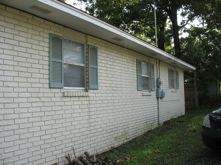
So, we decided to build some board & batten shutters. FUN! Now, if I only knew what board & batten shutters were…
Board & Batten Shutters – “Board & batten” usually refers to vertical siding where wood strips (or battens) hide the seams where other boards are joined. Here’s a site that has a lot of examples of the different styles of board & batten shutters.
After figuring out what they were exactly, I looked up a design and built them. I’m not going to go into detail on how to build them, because frankly, I screwed up too much to properly teach you. But, if you’re interested, here’s a tutorial from Lowes that matched with the style that I built.
Again, I had never done anything like this so, like a good lad, I went to where the experts were: DIY.StackExchange.com! This post is actually based on my question to them. Now, onto the process:
- Measure, level and mark boards, appropriately aligning the future holes with the mortar between bricks.
- Drill pilot holes into the wood shutters, including a 1/4″ countersink to cover the screw heads up with wood filler.
- What I learned: Unlike screwing wood to wood, where you can sink the screws into the wood easily without a countersink, when attaching wood to mortar, if you do not provide the countersink hole already and attempt to perform said action, you will strip the mortar and the screw will just spin and stay loose. Not good.
- Next, re-level shutters and mark the mortar with the masonry drill bit through the pilot holes. I found that only drilling the top two holes worked best for me. I’ll get to why in a minute. An extra set of hands comes in handy here.
- Set the shutter down and drill the top two mortar holes completely.
- What I learned: Be sure to drill into the mortar enough to where the screw tip won’t hit a dead-end (Most recommended a 1/16″ or 1/4″ of extra room beyond the screw tip). If you don’t give a little extra space at the tip, you’ll encounter a great deal of resistance, the screw will not go in all the way and you’ll have to get the masonry bit out again.
- Attach the shutter to the house using the top two holes.
- Now, we’ll finish the bottom two holes: with your masonry bit, drill into the mortar through the board.
- What I learned: I found this process to be the easiest for me, as my pilot holes didn’t always match up completely when I attempted marking then drilling all four at the same time. Less margin of error on my part. But, this is became a personal preference. Decide for yourself.
- Finish attaching the shutter to the mortar at the bottom with your screws.
- Use wood filler to patch the holes, lightly sand filler.
- Paint/stain/seal accordingly.
- What I learned: I had already applied a sealer to the back of the shutters before attaching them. I taped off my house using wide painter’s tape after they were up and it saved me a huge headache of cleaning sealer off my house with mineral spirits.

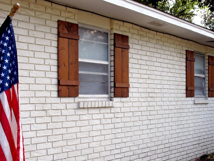
click to enlarge
Overall, I also learned:
- I marked & drilled all of the pilot holes into the shutters at one time which saved me on having to switch between the masonry & wood drill bits. HINT: If you forget to take out the masonry bit and attempt to drill into wood, you very likely could start a friction fire! Haha!
- Having two drills is a life-saver: I had my hammer drill set up with my masonry bit and my cordless drill had my Phillips bit in it ready for the screws.
- Having a second pair of hands throughout the entire process was also a great deal of help. Thanks, Seymour!
- The DIY.SE community is of great help!
Thanks for your help folks! I hope this walk-through helps someone else, too!

The Replacements – Swapping out windows in 2 hours or less
So I thought — “hey, you’ve got two replacement windows that need replacing – you should do a blog with a title like ‘The Replacments – Not the movie starring Kenau Reeves (however its spelled)‘”
Then I wrote the title and it looked dumb. Then I tried “The Replacements – Replacing old replacement windows with new replacement windows”… Yuck. “Replacing Replacements With Replacements” didn’t work either.
So I gave up. The title you see is the title you get – boring, isn’t it? Anyway – this is my second window focused article – and this time, it’s double hung!
We have a lot of replacement windows in our house that we didn’t install. I don’t know who did – but whoever did should be taken out and flogged. I’d never seen custom made replacement windows that didn’t properly fit their frames, until we moved in here. Several of our windows don’t lock properly, because the windows aren’t quite perfectly sized, so the lock never lines up. This we’ve lived with for some time – but of late, our windows are starting to fail. The clips holding the windows to the tension rods (the spring loaded bars that keep the windows in position) are failing, and when they fail, NOTHING is holding that window closed, except…

Yep – a piece of wood. Isn’t that awesome?
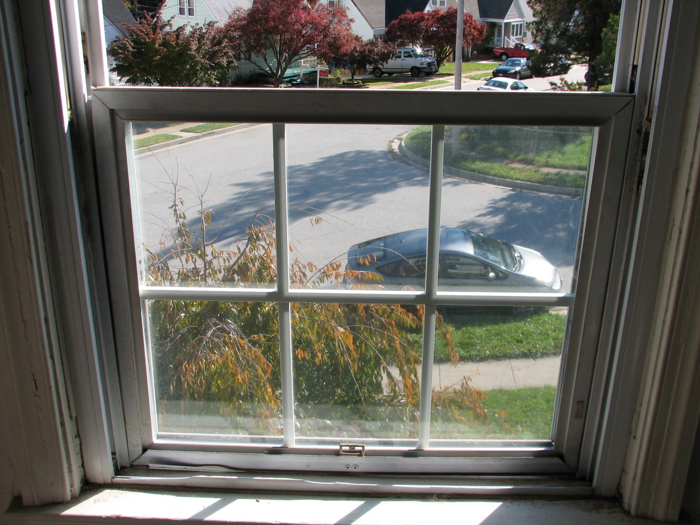
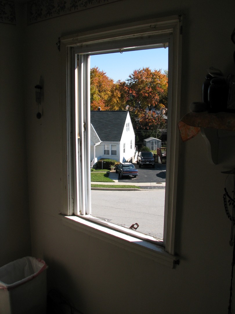
(By the way – this is our office window. Some genius forgot to take good “before” pictures – the bedroom window featured in the near future in this blog was actually worse…)
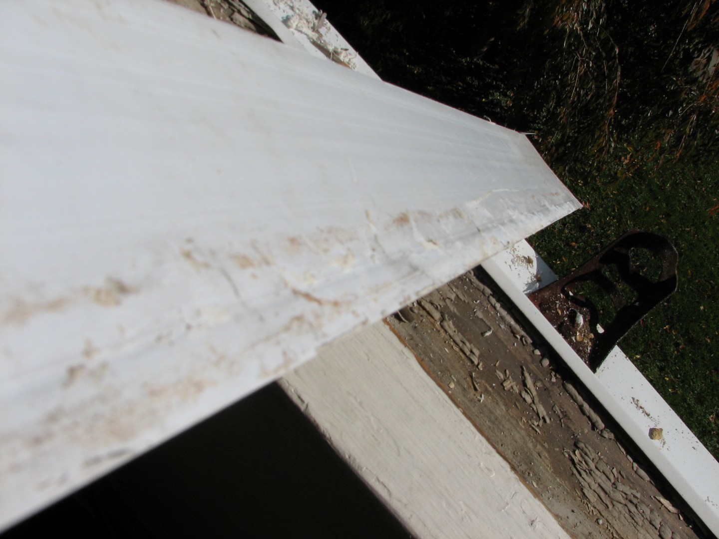
And of course, the window doesn’t exactly sit properly, so the top of the window looks like this:
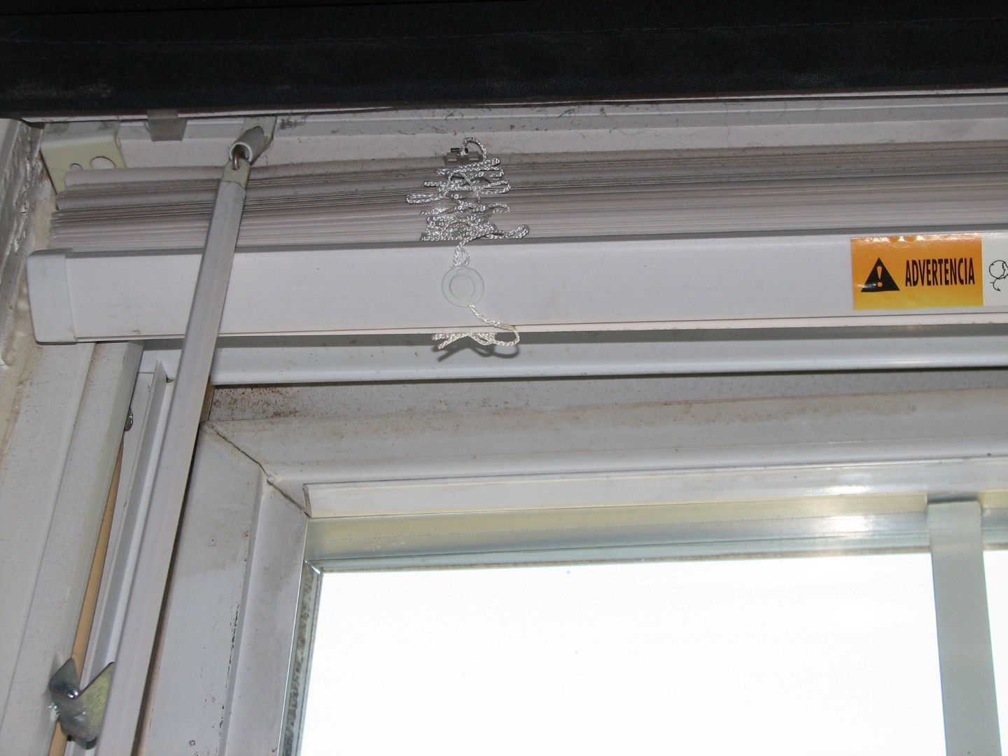
If it isn’t immediately obvious – look below the blinds, and you’ll see the irregular gap between the window pane and the frame. Talk about your heat loss!
Unfortunately, Congress hasn’t approved the “Evil Greebo TARP Bailout” program, so we’ve been limited in how fast we could buy replacement windows, but the GOOD news is, as we are able to bring them in, they go in fast, because we’re replacing replacement windows with new replacement windows.
So – here’s how it went.
First, I had to remove the old window. Our window tension clips have failed, so this was very easy, as all I had to do was remove the supporting wood and the top pane of the window fell to the bottom of the window at the speed of gravity:
By the way – I actually had to stop and go back and re insert the window pane so I could take this picture, because I forgot to start taking pictures right at the beginning of the project. I really wanted to show you just how bad this window was, but I wasn’t about to try and re-hang the dang thing just for a few pictures, so you’ll have to trust me, it was bad.
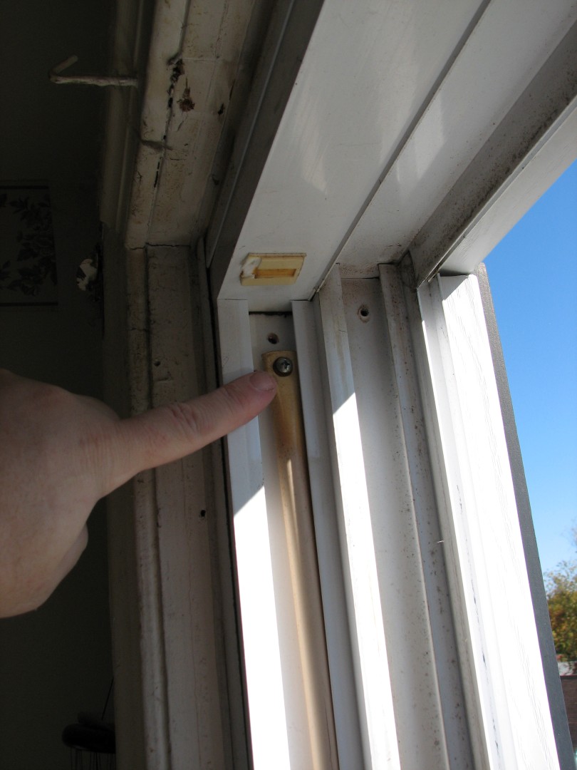
Ok, so how do you remove those panes, you ask? At the top of the pane are two clips. They look different depending on the model, but they’ll be right here:
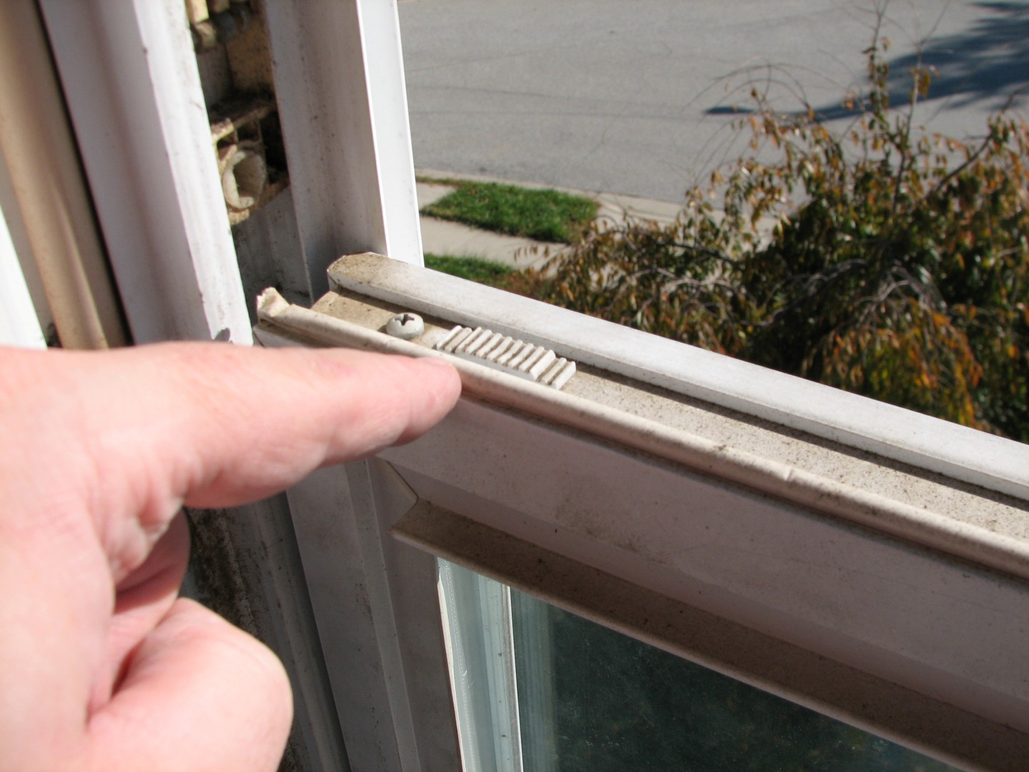
See? Right there by my finger. At the same time, open BOTH clips by sliding them towards the center of the window, and fold the window down towards you like so:
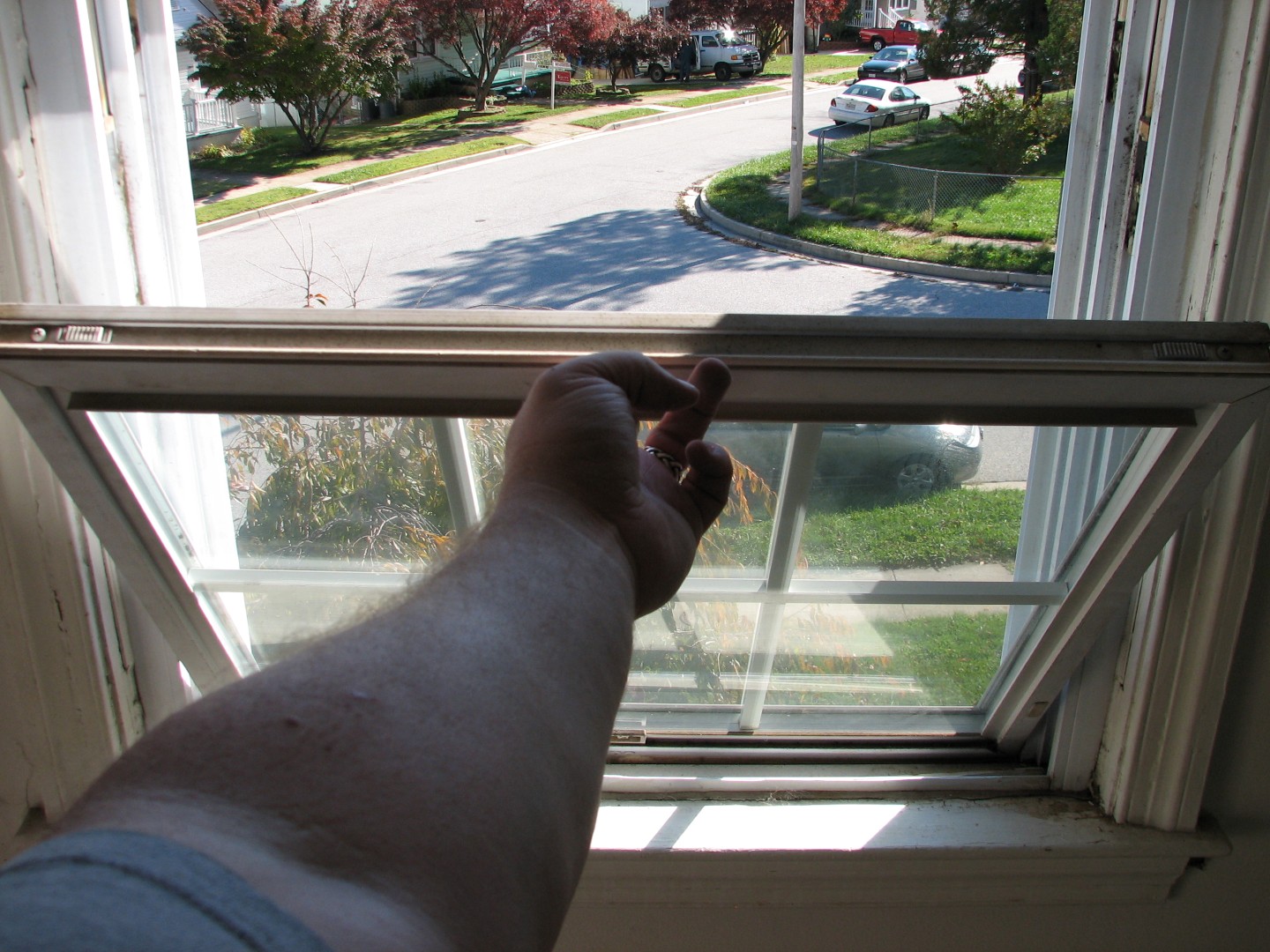
Now, husbands, if you get stuck at this point, ask your wives, because they’ve all done this hundreds of times in order to clean the windows, a task men are incapable of because, well, quite simply, we don’t care if the windows are dirty anyway, too much light blocks out the TV screen.
After you fold the window down to a 90 degree angle level with the floor, twist the window so that one corner lifts up and out of it’s clip, and the entire pane should then lift out easily.
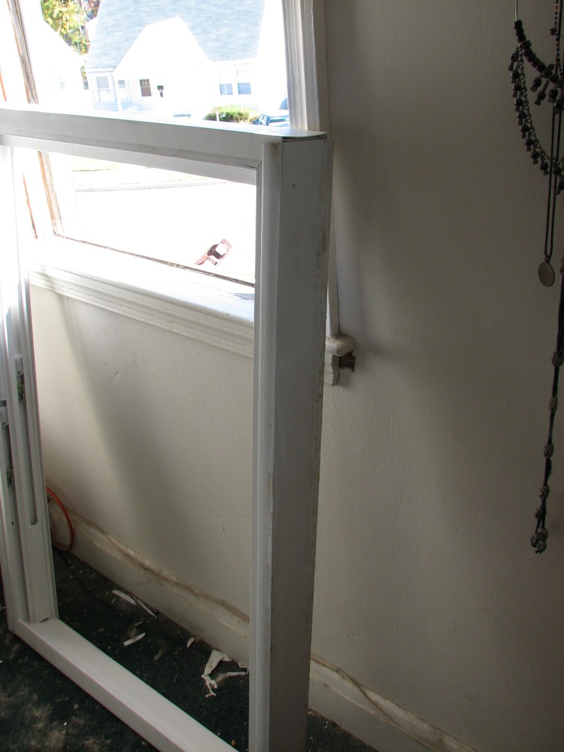
A windowless window:
By the way – note how my neighbors windows look so clean and neat? I’m so jealous. On the other hand, I can park properly…
So next up, since I was replacing replacement windows, I needed to remove the old replacement frame. Inside the window tracks themselves, at each of the four corners, are four screws:
I’m actually pointing at the tension rod in this shot – look at the hole ABOVE my finger – the one with no screw in it but lots of rust stains.
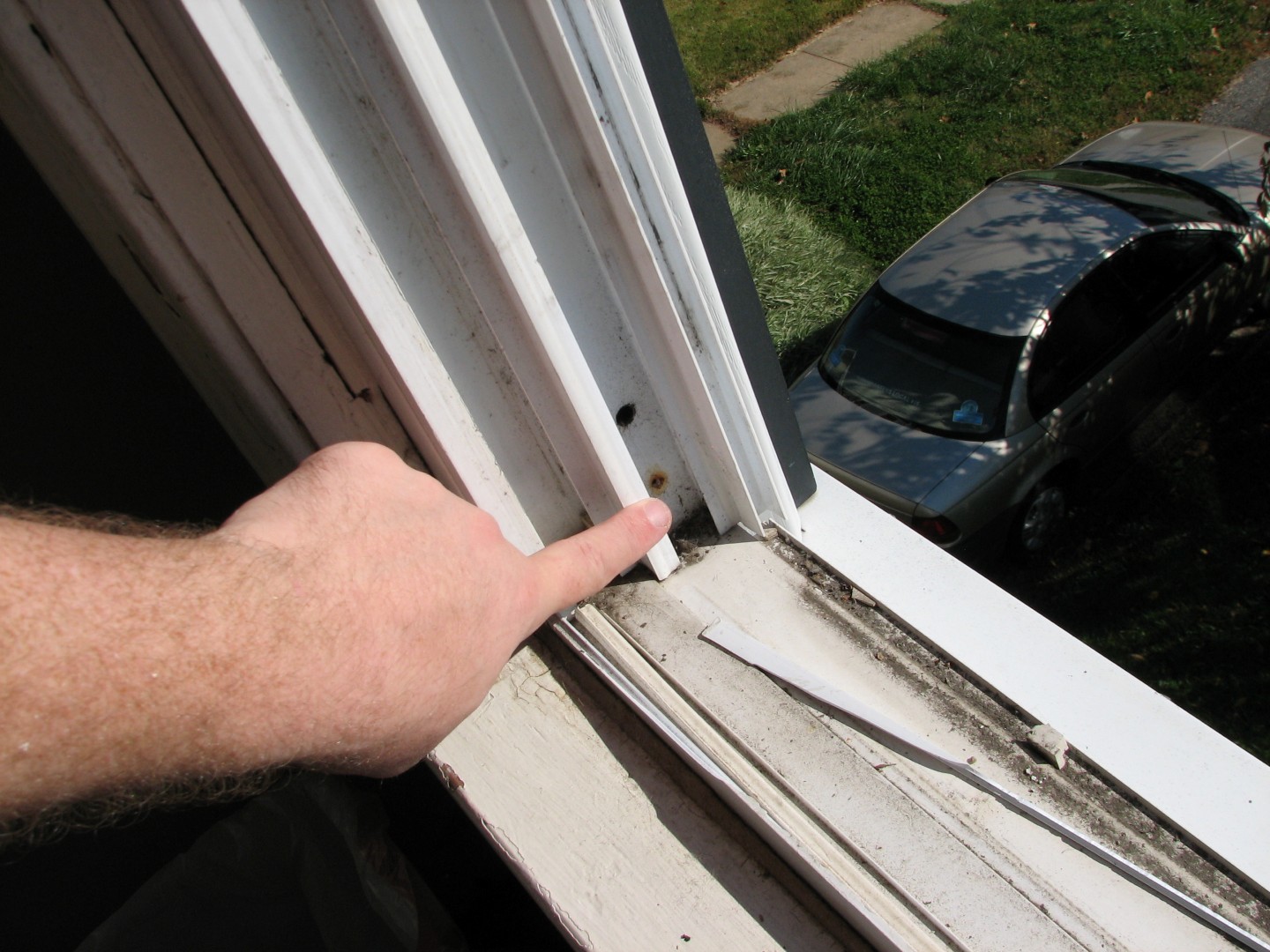
As you can see here, I’ve already removed the rusty screws for your convenience.
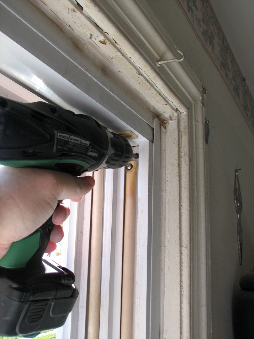
Here’s what they look like PRE removal (and by the way, guess at which point in the project I finally said to myself, “Hey, lets take pictures!” – Here’s a hint – this is window #2 of the day…I’m such a genius…)
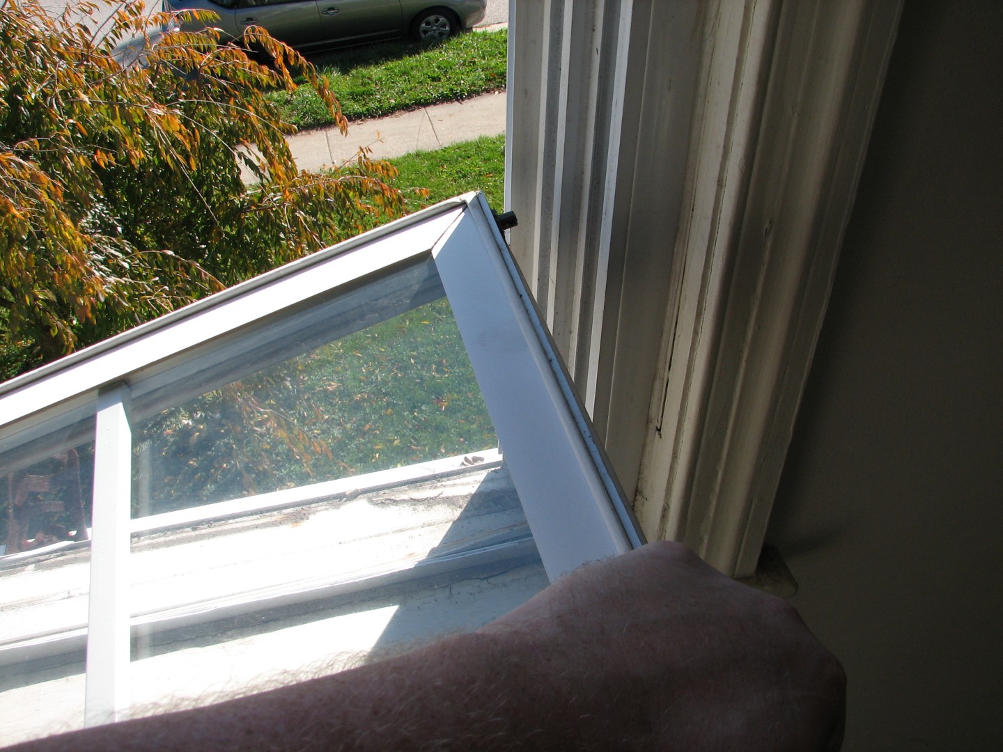
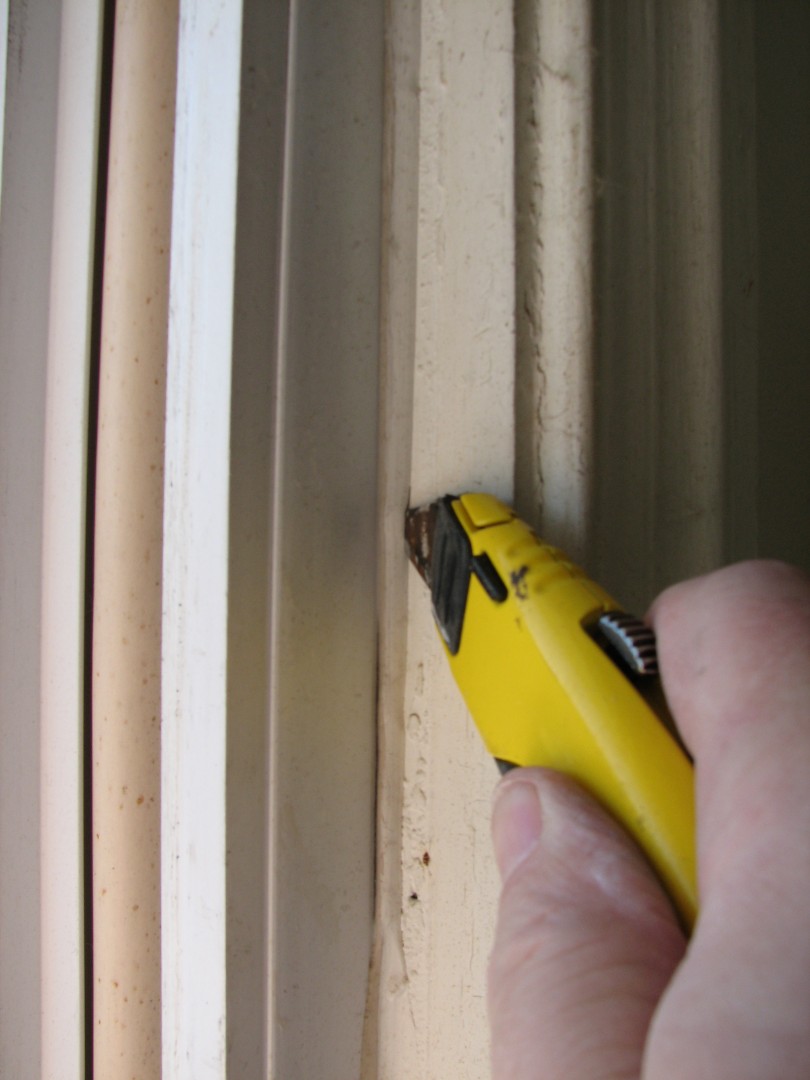
I removed the screws, and then well, see how where the old vinyl frame meets the old wood frame, there’s caulk? Normally that’s good, because it helps support the window and prevents leaks, but NOW its bad because, well, it helps support the window, and you are NOT getting that window out very easily if the caulk is still there. So, using a handy dandy utility knife and 1″ scraper I stripped the caulk or at least cut it to break the seal:
And then gingerly applying brute force, I yanked that old frame out of the wall. Care was necessary though, because I did want to save those vinyl channels the old window was sitting in.
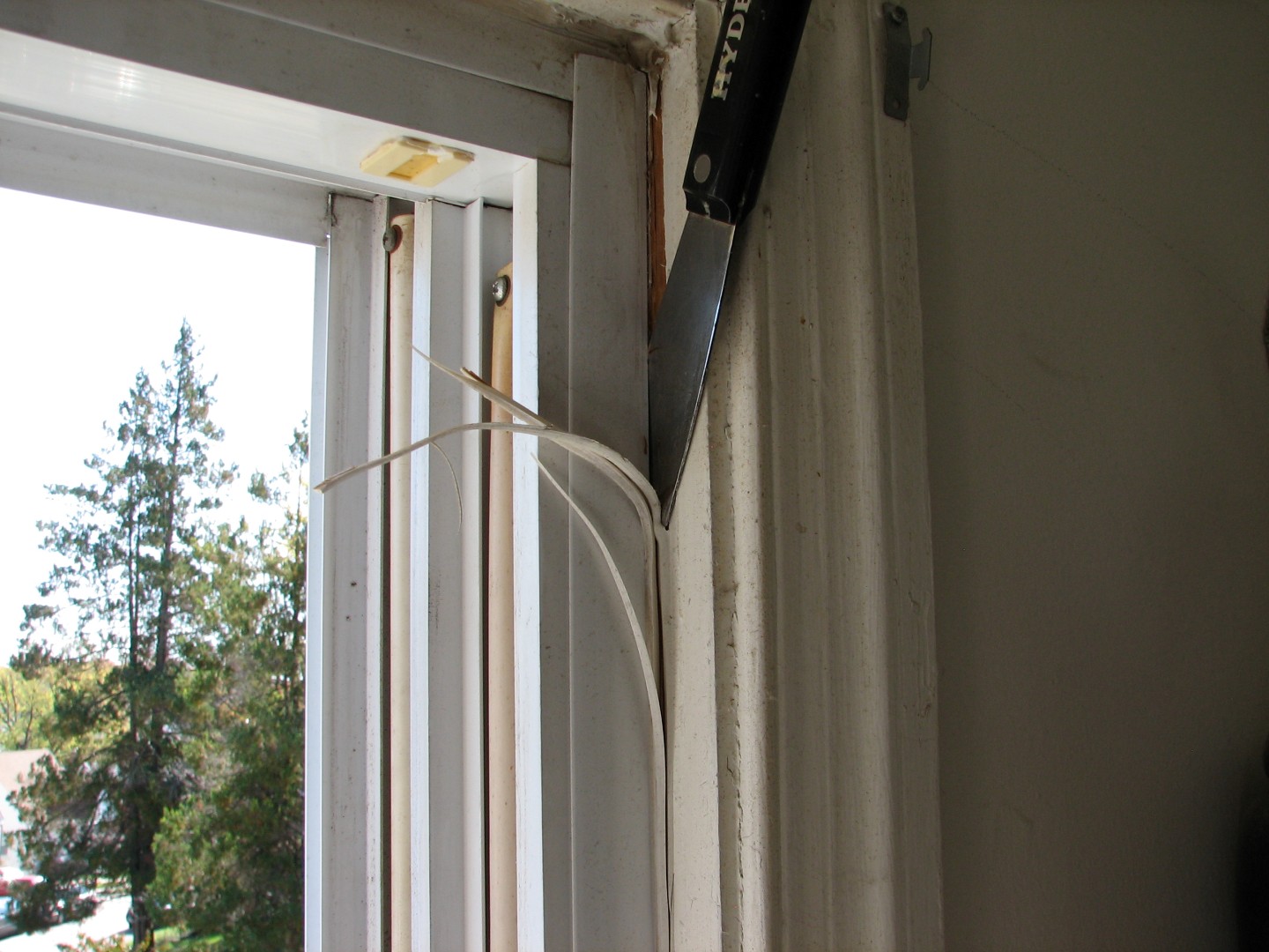
So once the window was out, in this case, I wanted to re-use the vertical side channels because they provided a nice clean look that didn’t require adding a lot of trim, but they were a MESS:
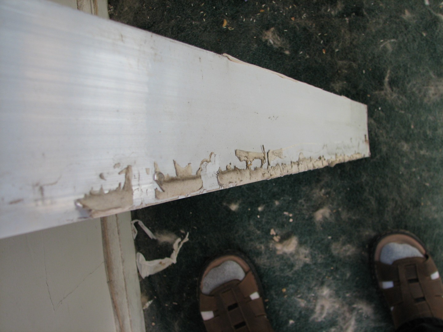
Yes, I wore tube socks with sandals. It was cold, my toes need protecting!
One of my favorite tools, the Bosch multi-tool, was PERFECT for cleaning this up:
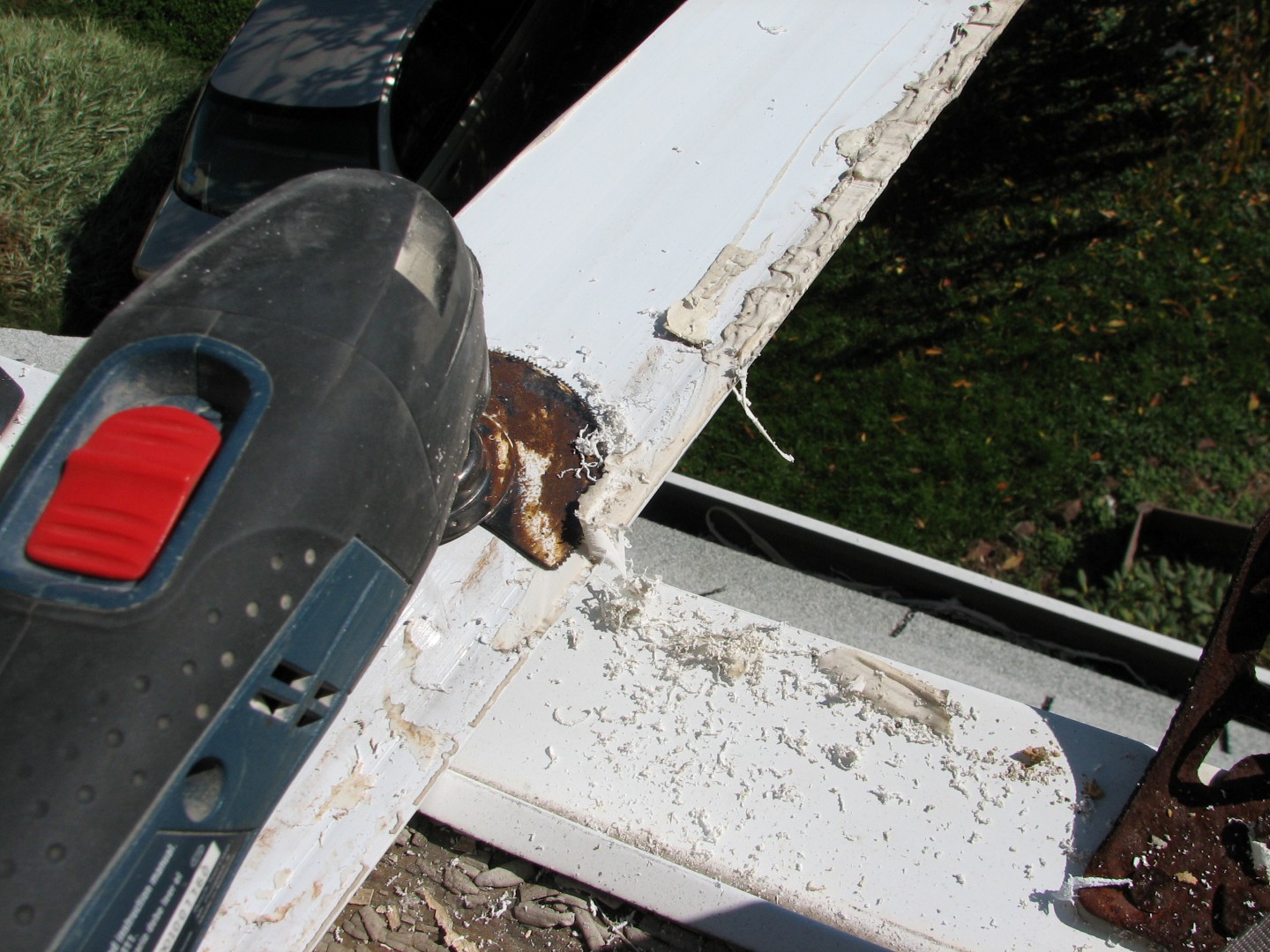
So pretty soon I had a nice clean channel to reuse:
Well, clean enough. 🙂
I’ve learned the hard way about dry fitting. For the uninitiated, this is the step where you put everything in place BEFORE you attach any glue, adhesives, screws, etc. Trust me, nothing sucks worse than getting the adhesive all spread out and then figuring out the piece you were installing doesn’t fit.
Here you can see, I’ve slipped the vertical and horizontal top channels onto the frame. The horizontal channel goes over top of the vertical channels on the outside of the frame, so on the inside, the vertical covers the horizontal. This is done so that if water hits the frame, it’ll run down off the top and onto the side pieces on the outside, rather than get inside the window frame.
And now, a gratuitous shot of one of our dogs, Lacy. She doesn’t like renovation work – the tools scare her.

See how nervous she looks? Or hungry. Probably hungry and nervous that I won’t give her food.
Ok so after test fitting the window, which was a perfect fit, it was time to make a more permanent install. Now you saw the rusty screw holes – shockingly enough, windows get exposed to water, so its smart to use weather proof screws:
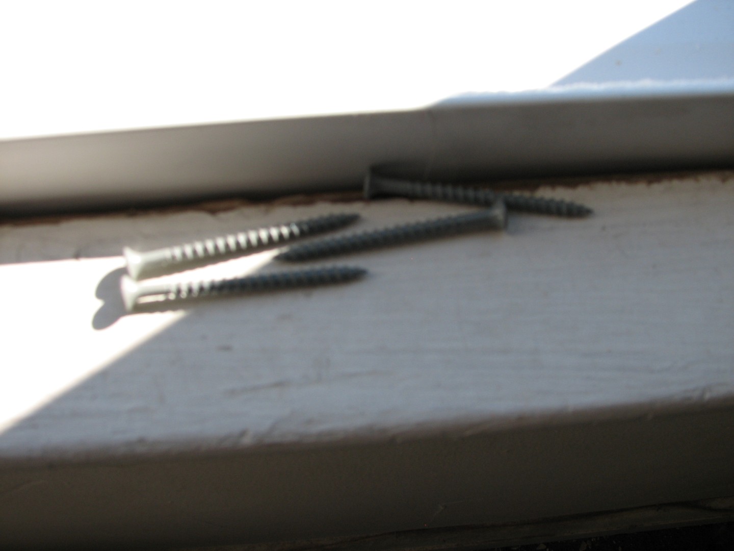
These are 2&1/2″ coated sinkers. Since this was a replacement window and I preserved the original sill, I put the frame back in the window and pulled the base forward as much as possible, then anchored one screw in the bottom at each side. If you do this, DON’T tighten the screw much – just get a bite in the frame. You need to be able to adjust the window for square and level and if you tighten them up, you’ll be sorry.
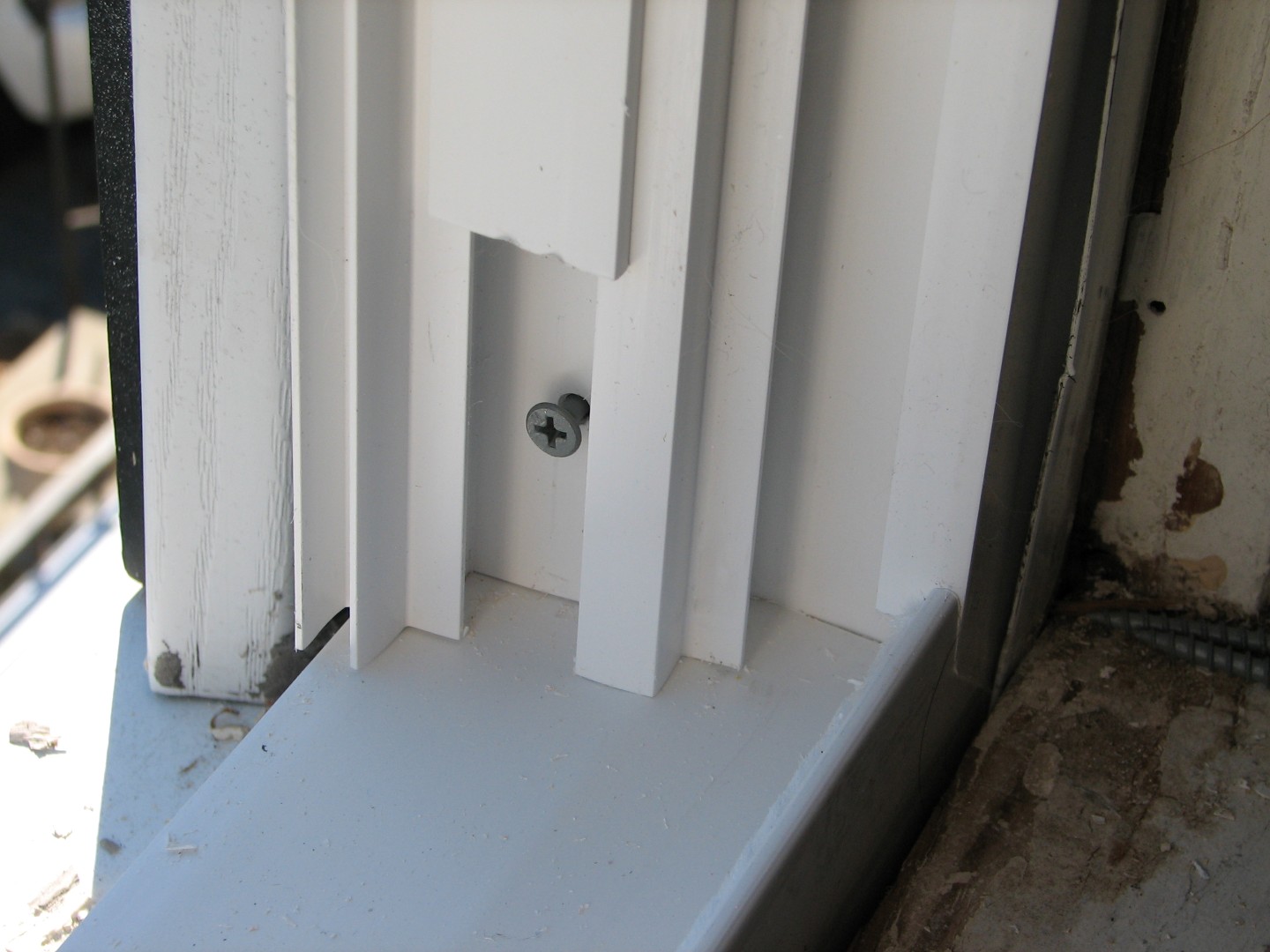
Next was getting the frame plum (ie: vertically straight) :
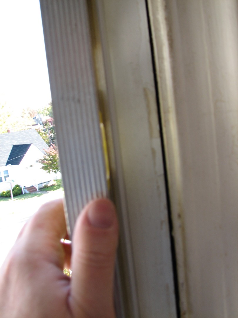
Once the frame was level it was just a matter of carefully tightening the screws on both sides to get it internally plum and perfectly rectangular.
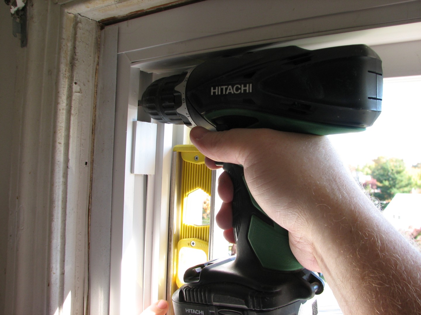
After that, it was a pretty simple matter of caulking (inside and out – nothing like hanging out the window of a 2nd floor building…)
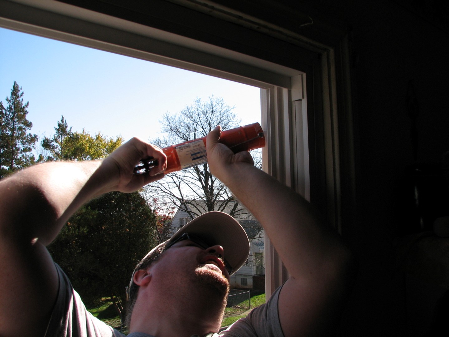
installing the screen and the two new window panes:
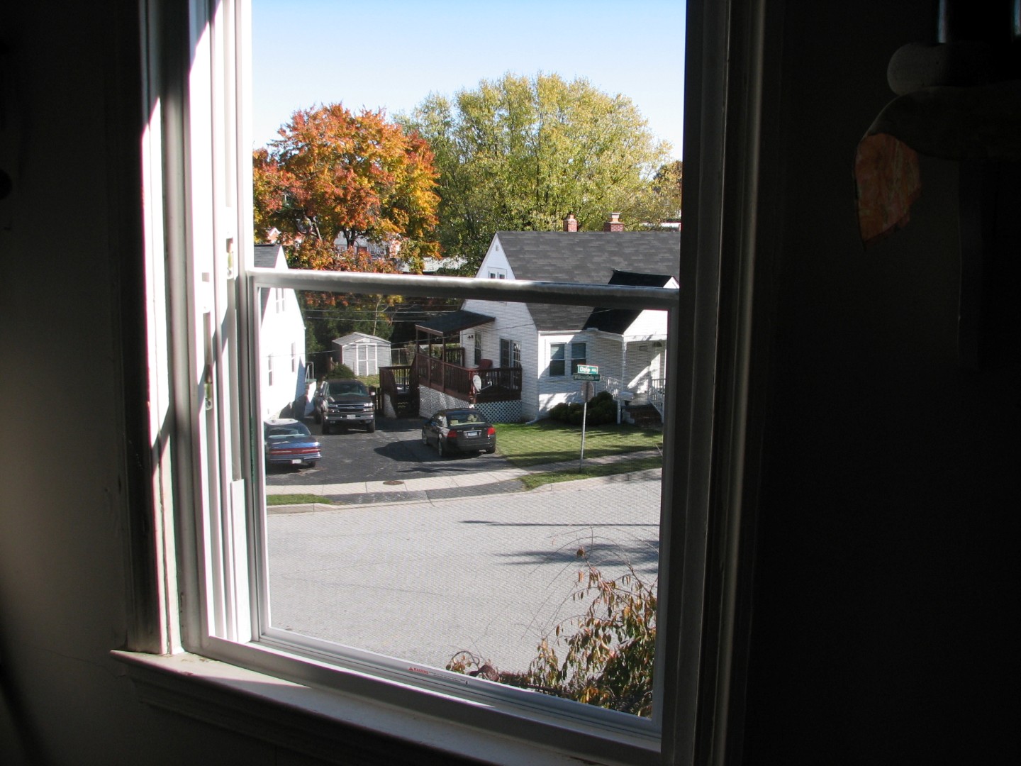
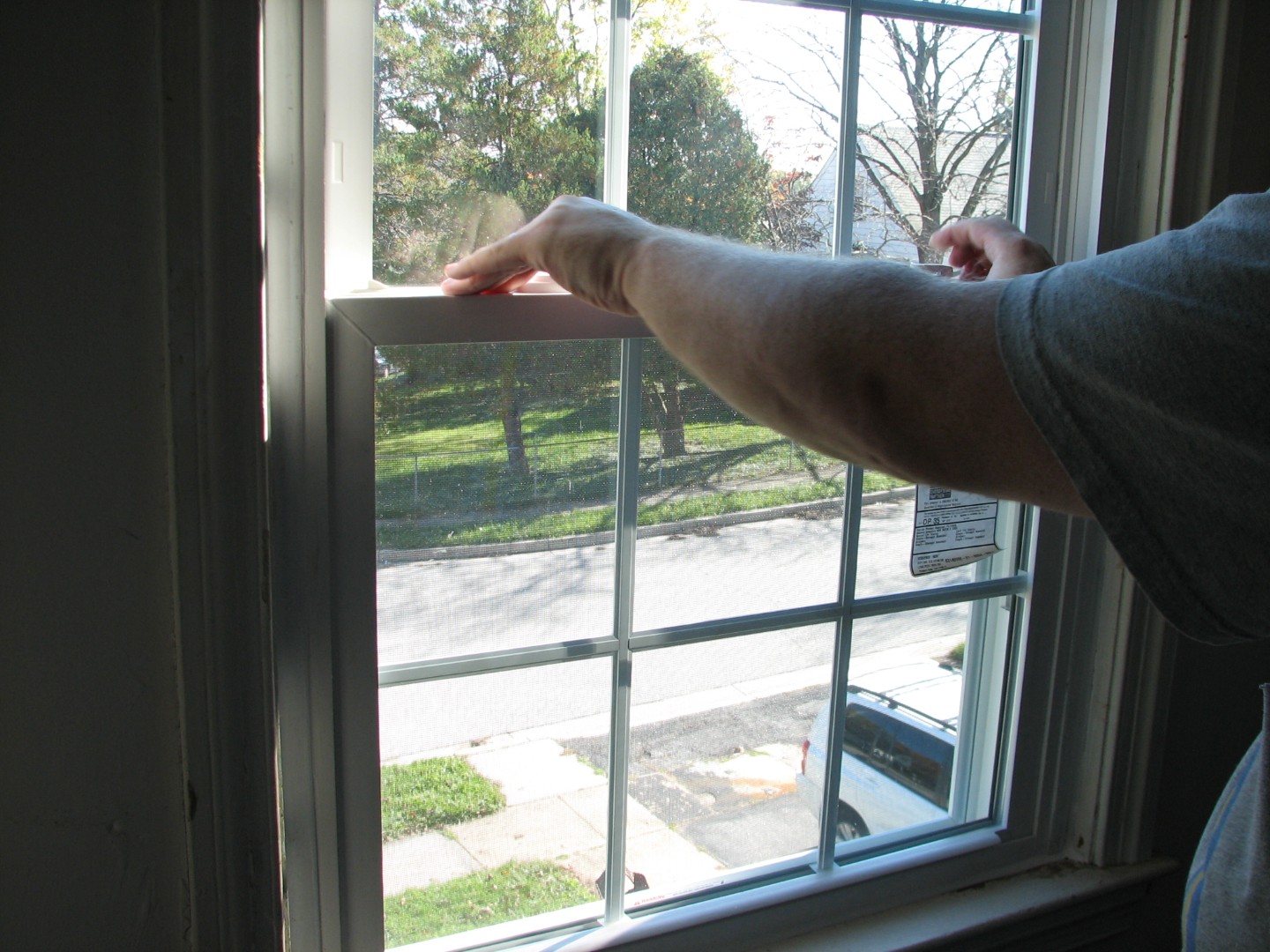
And finally, the blinds:
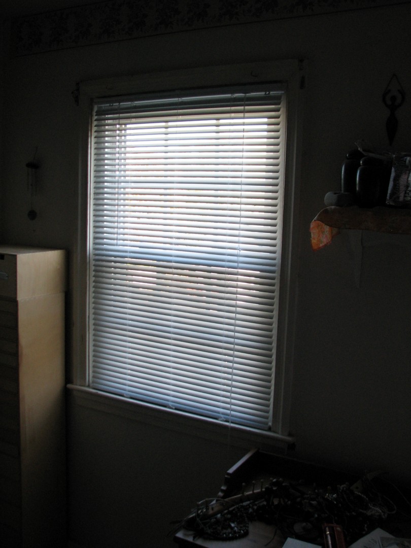
And viola! Two new replacement windows in the bedroom:
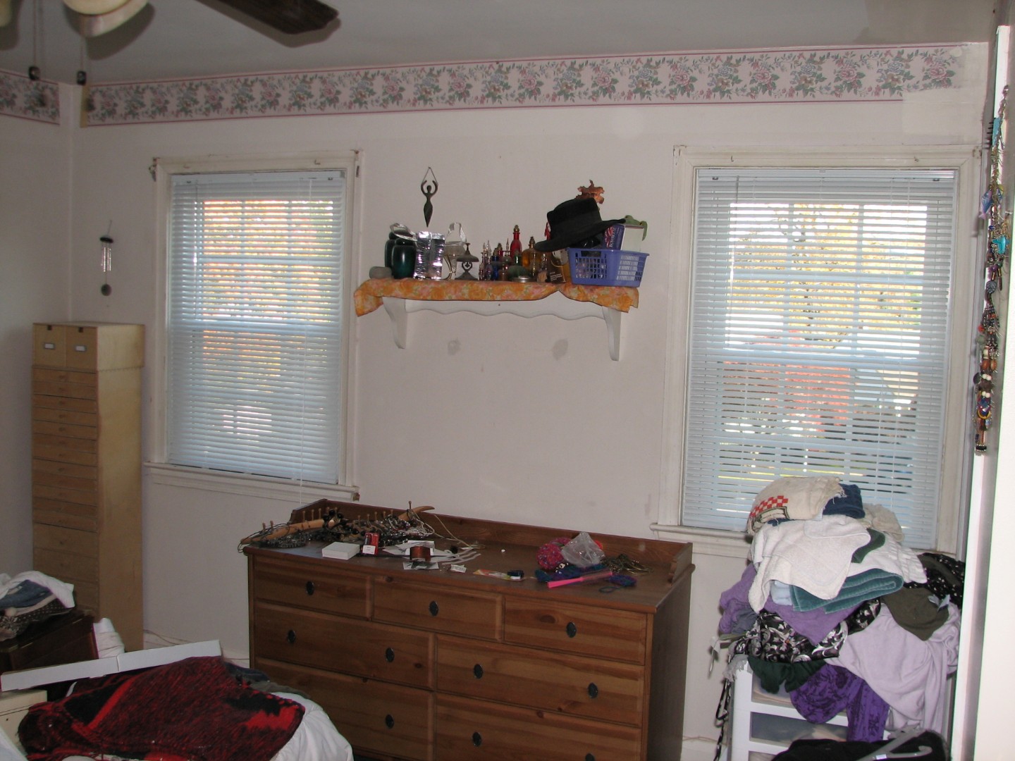
Lacy was exhausted! And so was I, but our new windows make our bedrooom warmer, quieter, and the low-E glass means less heat-loss in winter and the AC doesn’t need to work as hard in the summer! In fact it’s been so warm, we’ve got to crack the windows at night…
I’m sure that’s ironic somehow…
Hammer safely!
G

Home Improvement Blog on Google+
Home Improvement Blog on FaceBook
Bloggers Wanted
Latest Articles
Topics
- Electrical (8)
- Introductions (7)
- Plumbing (3)
- Projects (13)
- Repair (4)
- Safety (5)
- Tips and Tricks (5)
- Tool Review (5)
- Tools (6)
- Uncategorized (5)