Posts Tagged ‘Electrical’
Demystifying the mystifying GFCI
A commonly misunderstood electrical device, is the Ground-Fault Circuit Interrupter (GFCI). Whether posing as a circuit breaker, or a receptacle, the GFCI device is almost always misunderstood. To understand the GFCI, however, you have to know a bit (and I mean a really little bit) about transformers.
This is a transformer.
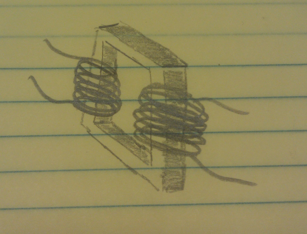
(Well, a crude representation of one anyway). It consists of an iron core, and a couple coils of wires.
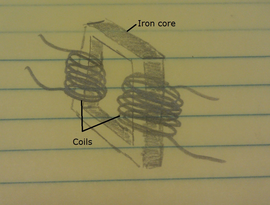
More specifically, it has a primary coil of wire, and a secondary coil of wire.

When you place a voltage on the primary coil, some magnetic magic happens in the core and a voltage is induced on the secondary coil.

And there you have the most basic crash course, on the most coarse basics of transformers. Which is all you need, to understand how GFCI devices work.
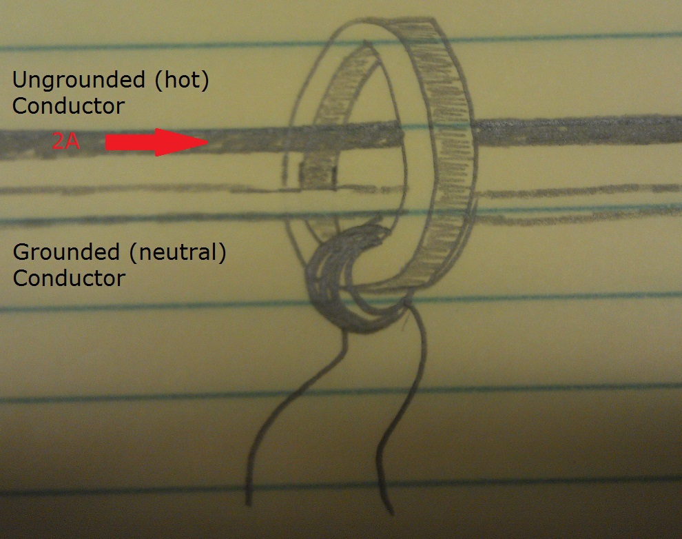
Inside a GFCI device, you’ll find what’s called a Current Transformer (CT). A crude representation of a CT, looks something like this.
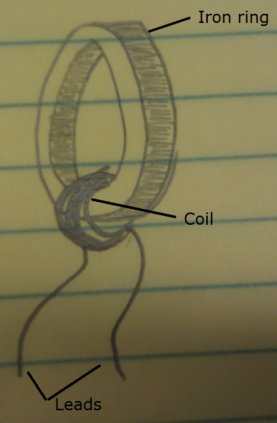
A CT works just like any other transformer. When a voltage is applied to the primary, a voltage is induced on the secondary. The only difference, is that the primary isn’t a coil, exactly. The primary is instead the ungrounded (hot), and grounded (neutral) conductors of an electrical circuit.
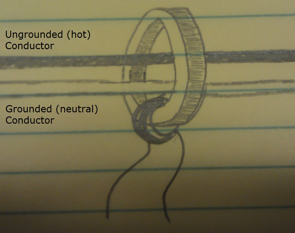
When current is drawn on the circuit, it flows down the ungrounded (hot) cunductor. Out to the consuming device, then returns back to the source on the grounded (neutral) conductor. Similarly, if we draw current from a GFCI device. It flows down through the ungrounded (hot) conductor, and through the CT core.
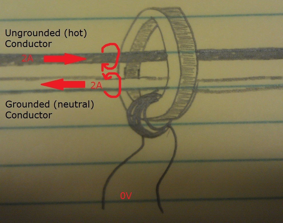
The current then flows back through the CT on the grounded (neutral) conductor, and back to the source.

According to the right hand rule. If you point the thumb of your right hand in the direction of current flow, and wrap your fingers around the conductor, your fingers point in the direction of the magnetic field produced by the flowing current. If this is done with the above diagram, we end up with magnetic field lines like this.

Because of the proximity, and opposite-ness of the fields. They cancel each other out, and no voltage is induced on the secondary coil of the CT.
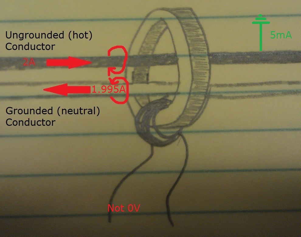
In the case of a ground-fault, however, not all the current will flow back along the grounded (neutral) conductor. This creates an imbalance in the magnetic fields, which allows magnetic magic to occur in the transformer core, and a voltage is induced on the secondary of the CT. If the voltage on the CT is large enough, and lasts long enough, the GFCI device will open the circuit.
Next time you come across a GFCI device that continually trips, think about how it works and what it’s looking for. This might give you a better idea of what to look for, and where to start troubleshooting. And remember to always work safely, and cautiously whenever you’re working with electricity.

Knowing when to say when
One of the most important skills a do it yourselfer can have, is knowing what you can do yourself and what you can’t. While doing work yourself can often save you a bit of money, doing things wrong can cost you more than you might think. Admitting to yourself that you can’t do something is often a very difficult and frustrating task, but realizing you shouldn’t have done something yourself can be much worse.
Trying new things is one of the best ways to learn what you can and cannot do, so you should never be afraid to try things. Learning a new skill or finding that you can do more than you thought, can be a great feeling. The best way to try and learn new things, is to do so under the supervision of a person who already knows how to do those things. Most community colleges; and some big box hardware stores, offer courses that can teach you how to do things yourself in a safe environment. Learning a new trade can be much easier in a risk free environment, where failure only means that you have to try again. Maybe you have a friend or family member who is knowledgeable in this field, and is willing to teach you what they know.
The worst place to learn a new trade is in the dark, crawling through mud, at 4:00 A.M., in a cramped space, with your family yelling at you because the water has been shut off for 12 hours. Learning in a situation like this only leads to mistakes, frustration, and failure, so you should make sure you’re comfortable with the work you’re about to do, and confident in your ability to do it, before you begin.
While almost any job around the house can be a do it yourself task, some jobs require more training and a good understanding of the underlying system to be completed successfully.
Plumbing
While some plumbing jobs require only a small amount of skill (changing a faucet, unclogging a drain, fixing a leaky toilet, etc.), others require training, planning, skill, and experience. Some aspects of plumbing can be done by almost anybody, but may only be done well by an experienced tradesman. Soldering joints, for example, is a task that can be done by almost anybody, but only a true master can do it artfully.
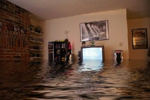
Plumbing is one of those things where you might think “You just connect pipes, how hard can that be”, until you end up with a stream of never ending water flooding your basement.
Plumbing is one of the vital systems in your home, which goes unnoticed most of the time but can cause a lot of grief when it’s not working. You might think “I’ll just shut off the water, make this connection, and I’ll be done”. Then you find yourself 6 hours later, standing in a puddle, dripping wet, with your legs crossed trying not to soil your pants.
The best way to learn how to plumb, is to do it where there are little to no consequences. Soldering scrap pieces of pipe in the garage, is a great safe way to learn to solder. Practice these skills before you start working on such a vital system in your home. Spend some time figuring out exactly what you’ll have to do to complete the job, then make a good plan and stick to it. Do as much work as you can before you shut off the water supply, this will minimize the systems down time (and help you avoid soiling your pants).
Electrical
This field of work requires at least a slight understanding of how electricity behaves in order to be able to complete simple tasks such as replacing receptacles, changing light fixtures, replacing switches, and other small activities. However, most jobs require a fairly good grasp of electrical concepts, electrical codes and best practices, and some form of training. This is not a trade for novice do it yourselfers, and in most cases work should be completed by; or at least inspected by, a capable, licensed Electrician.
Becoming capable of doing electrical work yourself will require fairly major investments in both learning and tools, so be prepared to spend a lot of time and money if you are thinking of tackling these types of jobs.
The basics of electrical work can be learned relatively quickly, but the knowledge required to complete tasks grows exponentially as you become more involved with larger sections of the electrical system. Learning to replace a light fixture can be quick and easy. Learning to install and troubleshoot whole circuits, can take a long time and require a lot of specialized tools.
Electrical work can be very dangerous, and can cause personal injury, death, and/or property damage if done incorrectly. This is why training, and a good understanding of the basic concepts is so important. Do it yourselfers should have a fairly good understanding of how electrical systems work, and what tools are required, before deciding if they should complete any electrical work themselves.
HVAC
Heating ventilation and air conditioning jobs often require both plumbing and electrical skills, and apart from minor jobs (replacing a thermostat, changing filters, etc.) they should not be preformed by unqualified persons. HVAC systems can cause personal injury, death, and property damage, if not installed and maintained properly. It requires an in-depth knowledge of the systems involved to safely complete HVAC jobs, which often means this type of work should be avoided by a do it yourselfer.
This type of work will require training, specialized tools, and a solid understanding of electricity, plumbing, fluid dynamics, thermal dynamics, high and low pressure systems, and electronics.
While there are other dangerous systems and jobs throughout the house, electrical, plumbing, and HVAC can be the most hazardous for do it yourselfers. With the high prices that professionals in this field charge, it’s often tempting to try and avoid these expenses. In most cases, however, it’s safer and more cost effective (in the long run) to simply allow a professional to complete this type of work. Saving a few dollars, is never worth risking your families safety and well being.
Ground Fault Current Interrupters
Ground Fault Circuit Interrupters (GFCI) have been part of the NEC code for over 40 years now and just like your car, things have changed. Over the years the code has changed but also makers of GFCI and Underwriters Laboratories (UL) have made a lot of good changes. Life saving changes that probably nobody except a few electricians have noticed. Today, most people just think of the GFCI in their bathroom or kitchen and will probably never know all the great GFCI that are available.
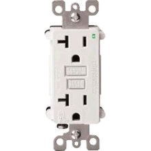
Today, the s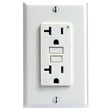 tandard GFCI that you see in your wall is either 15 or 20 amp and the most noticeable feature you see is a light, usually a little green light. If you don’t see the light or the light has changed colors then your GFCI will not work. What you don’t see is that GFCI are self testing every 15 minutes. A trip can be reset, but a failed GFCI will not reset and you will have to replace the GFCI. Another feature is that the GFCI comes from the factory in the tripped position and if it is mis-wired you will not be able to reset the GFCI until it is corrected.
 Did you know there are tamper resistant receptacles and GFCI? Now manufacturers make tamper resistant GFCI for your children’s bathroom. These meet the same stringent requirements of a standard GFCI, but now somebody cannot just stick something conductive into any slot of the GFCI. Now you can sleep better at night knowing your kids are safer. The tamper-resistant receptacles and GFCI have been NEC code since 2008 but not all municipalities are enforcing it yet.
Now you can buy weather resistant GFCI. It will still have to go in a weather resistant cover or even a bubble cover. Weather-resistant GFCI are made to go outside, being able to take extreme temperatures, UV and moisture. The weather resistant GFCI are also made with the tamper resistant feature.
Faceles s GFCI are also made. This is just GFCI made with only the test and reset buttons, no receptacle built in, like it’s name implies.
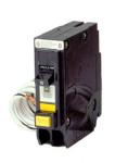
Another faceless GFCI is the high current GFCI which can handle up to 80 amps at 240 volts. These feature a current sense transformer called a donut which is powered by 120 volts. If you need a GFCI for your spa or equipment and cannot find a breaker, then these will come in handy. The high current GFCI should only be installed by a licensed electrician.
Do you need a night light or a guide light? GFCI are made with a receptacle and a light. A photo sensor turns the light on and off. How about a pilot light with your GFCI? The light comes on when there is a load on the GFCI. Comes in handy in basements with sump pumps. All the lights are LED for low power consumption and long life. Do you need a switch and the only room is a GFCI? Replace the GFCI with a combination switch and GFCI. The switch is independent of the GFCI and can turn on that vent or light. These combination devices can also be purchased with the tamper-resistant feature and no safety feature has been removed.
There are other GFCI made like extension cords with GFCI, or GFCI that can be wired in as the plug of an extension cord. Panel mount GFCI are available for sump pumps, generators or temporary power.
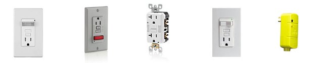
Night Light GFCI, Pilot Light GFCI, another Night Light, Switch Combo, and Cord GFCI
While this might not have been the most exciting read you’ve had today, I hope that this might help on your next DIY Home Improvement Project.

Enjoy the blog? What to be a part of the action? There are many ways to Contribute to the Blog.
Arc Fault Breakers
Before we get into Arc Fault Circuit Interrupters (AFCI), let’s look at their uncle, the Ground Fault Circuit Interrupter (GFCI). GFCIs first appeared in the NEC code in 1971, and then only for swimming pools (not spas) and exterior outlets. Today, bathrooms, kitchens, wet bars, garages, rooftops, spas and any place that water can be a problem must be protected by a GFCI according to code. Without getting into what a GFCI does, it basically can save your life. This has been proved over and over, and unfortunately also proved when GFCIs have been removed, tampered with, or failed.
Let’s start off with some questions:
What is an Arc Fault? An arc fault is when current goes through your wires and somehow takes an unintended course that produces a spark, or arc.
Why don’t my regular breakers protect me from arcs? Your breakers protect you, but what an AFCI does, that a regular breaker can’t, is detect a very low level arc. If not detected, that low level arc could quickly become a life threatening event – in your house!
Why do I need AFCIs and GFCIs? A GFCI protects you and others from fatal electric shocks when a ground fault happens, like if you try to make toast while taking a bath and drop the toaster. That would be a ground fault due to water. As explained above, an AFCI protects you and your valuables from a potential fire caused by a low level arc.
What causes arc faults? Worn or damaged wire; damaged plugs or receptacles; loose electrical connections; screws, nails or staples driven into wires; furniture pinching lamp or appliance cords; broken wire; frayed wires; and even wire chewed on by your pets. Probably anything your kids do when you’re not around. The NEC uses the term combination to describe fault protection. This covers both parallel arcs (two wires arcing together) and series arcs (arc caused by one wire arcing between two damaged areas)
Can I buy AFCI receptacles? Not at this time. Breakers will protect everything downstream from the breaker, but an AFCI receptacle would not protect the wire between the receptacle and the breaker.

Cause and Effects of Arc Faults
Whether you need AFCIs or not depends on your local codes. Not all local codes have accepted AFCIs as code, and some might accept them but not otherwise be up to the current national code. The current NEC Code, 210.12 says “All 120-volt, single phase, 15- and 20-ampere branch circuits supplying outlets installed in dwelling unit family rooms, dining rooms, living rooms, parlors, libraries, dens, bedrooms, sun-rooms, recreation rooms, closets, hallways, or similar rooms or areas shall be protected by a listed arc-fault circuit interrupter, combination-type, installed to provide protection of the branch circuit.” Even if your local code does not call for it, you still can install AFCIs in your home. Of course, if local code requires AFCIs then they will have to be installed on new homes and remodels.
AFCIs keep improving, just like GFCIs. With these improvements, specifications change and an older AFCI might not pass on a new job, depending on when the permits were issued. Just because a breaker says AFCI on it, that does not mean it will pass inspection. Your electrician will know which ones to use and your local code office will also have that information.
Tool Review: Ideal Lil’ Ripper Stripper™
I recently picked up the Lil’ Ripper Stripper™ from Ideal Industries, at Home Depot for about $5.00.
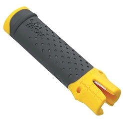
Not that I needed a new tool, especially another wire stripper; but for $5.00, how could I resist?
Really, I was just interested to see how useful it actually was. I’m almost always skeptical of multi-tools, since they aim to replace tools designed specifically for a single task. The Lil’ Ripper Stripper is no exception, so it really has to preform well to replace tools in my tool pouch.
Features:
- Rips Romex® wire outer jacket cleanly and quickly.
- Clips outer sheathing to remove excess Romex® wire jacket.
- Strips inner conduit wires.
- Looping holes loop wire for screw-on connections.
- Twist-Assist™ tightens most popular sizes of winged twist-on wire connectors.
- Injection molded elastomer grip provides a comfortable, slip resistant grip.
- Strip length measuring scale allows for quick and easy measurements.
- Conveniently fits in your pocket.
Since Ideal gave me a good feature list, lets tackle each one individually.
Ripping Romex® (NM wire)
The Lil’ Ripper Stripper, makes ripping non-metallic cable sheath simple and fast. If you look in one end of the tool, you’ll notice a small metal hook.

To rip the cable, simply place the hook under the cable sheathing, then slide the tool along the cable. The Lil’ Ripper Stripper definitely earns this part of its name, this thing rips cable like a champ. It slices through the sheath clean, fast, and without any concern of nicking the conductors. Because of its shape and size, you can even easily rip the sheath from cables already installed in boxes.
Removing excess sheathing
To remove the excess sheathing, you slide the sheathing into the large notch, at the end of the tool, and pull.
This feature seemed like an afterthought, or maybe the cutting blade was relocated to accommodate another feature. Either way, it’s not great at this. The cutting blade is set back a bit too far, which makes getting the excess sheath deep enough to cut it a challenge. Even the guy in the demo video had trouble with this feature, so it doesn’t seem to be user error on my part.
Stripping conductors
To strip the conductors, you simply slide the wire into the V notch at the end of the tool, give it a couple twists, then pull the insulation off.

It works relatively well, though it can easily nick the conductors if the wire is inserted too forcefully. You’ll also notice a measuring scale on the face of the tool, which helps you determine how much insulation to remove.

Terminal loops
To create terminal loops in the wire, you insert the wire into one of two holes on the side of the tool, then give it a quarter turn.

This is a nice feature, and works very well.
Twist-Assist™
To twist on wire caps, insert the cap into the end of the tool, insert the wires into the cap, then twist. This is a handy feature if you’re working in gloves, and find it difficult to twist on little wire caps because of it. The length and size of the tool give you a little extra grip, allowing you to twist on the wire caps without a problem. It’s only designed to work with winged wire caps, so if you’re working with caps without wings, you’re out of luck.
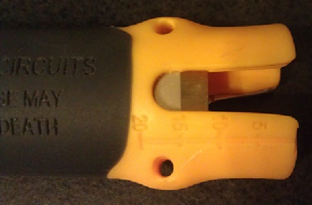
Comfortable, slip resistant grip.
The tool is comfortable in your hand, and it does provide a slip resistant coating. However, the best part of the grip is the constant reminder that you shouldn’t be working on live circuits.
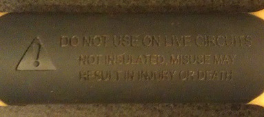
DO NOT USE ON LIVE CIRCUITS Not Insulated, misuse may result in injury or death
Conveniently fits in your pocket
Yes, it does fit in your pocket. But guess what Ideal… I want it to hang from my tool belt! Is it too much to ask for a key chain loop, so I can hang it from a carabiner on my tool pouch? I guess then they’d have to charge $5.50 for the tool, and maybe that’s too steep for the average DIYer.
All in all, this is a fairly nice tool. It would be a nice addition to any DIYers tool belt, er… pocket. It rips cable sheath really well, strips wires, makes terminal loops, and helps twist on wire caps. It’s a useful, sturdy tool, but I’m not sure I’m ready to give up my wire strippers just yet. For a DIYer looking for a useful inexpensive tool, this is a good solid choice. The Idea Lil’ Ripper Stripper gets 3.5 Captain Constructions, out of 5.

Fluorescents and Legislation, Part II
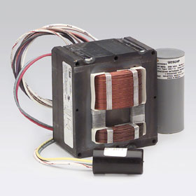
The death of the Plain Jane fluorescent tube is in the cards. Lighting legislation signed into law in 2007 has been coming at us for 5 years. Fuel economy for vehicles, bio-fuels, lighting fixtures, lamps, appliances and building energy savings were all targeted, along with other items too numerous and way over my head. In 2010, manufacturers were no longer able to manufacture magnetic ballast. These were the coil and core ballast that weighed a ton.
When suppliers started to run out, your only choice was electronic ballast. You know, if you’re old like me you can remember when those ballasts stuck their heads out in the 70’s, and after all the smoke from lawsuits and finger pointing cleared, they hid their ugly heads for 25 years. In 1995, when you took your 40 watt ballast to the hardware store, it had to replaced by a 34 watt. Now when you take your 34 watt ballast in, you get this little lightweight thing to put in your fixture. “How can I be getting my money’s worth? This thing is too light!”

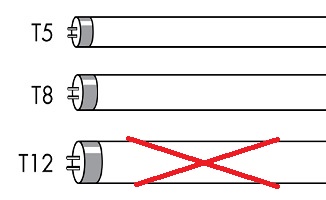
In 2010, if you had to change your fluorescent fixture, you had to start using those skinny tubes. “Light-weight fixtures and skinny tubes,don’t take me for a fool!” Starting July 14, 2012, the manufacturers will stop making all the old fashioned T12 lamps. With a few exceptions, when you take that 8 foot tube in your garage to get it replaced, or that wimpy 34 watt 4 foot tube in to get a replacement, not only will you have to buy a new fixture, you will also have to take the evil old lamps back with you, because they are now hazardous waste. “These kids now-a-days don’t know nuttin!”
If you are one of the few that read the “Energy Independence and Security Act of 2007” you might make heads or tails of it. If you understood it, then English must be a second language. But the good news is: it’s working for the most part. It is costing us an arm and leg, but it’s working. Now when you and I have the simple job of changing light bulbs, it becomes a major DIY project. It is costing us. Now what do we get out of it? More power. Since it has security in the title, do we get to carry a gun? Heck No!
Out of all the energy used in the US, 25% is used in homes and 19% is used in commercial buildings. It was estimated that energy use would spike 44% from 2005 to 2030. Seven years later it looks like that spike will only be 14%. If you do your math like our politicians, we will save 68%. But it’s 68% of nothing, and this time nothing is a good thing. You can look at it and say we saved 68%, or you can look at it and say we created 68%. It’s not from some new wind, sun, aluminum foil technology, it is a new technology. A technology called “Renewable Energy”.
Now, when you do your honey-dos, whether it’s caulking, insulating, installing blinds, or sitting under the shade of a tree you planted years ago, you know that you are pioneering new grounds.
On the numbers I used, I didn’t just grab the first numbers I found, I did try to check their sources. Probably the best source is EIA Annual Energy Outlook 2008.
Light Bulbs and Legislation
 I’ve been in the electrical wholesale business for almost 30 years and every day I sell light bulbs. For over 30 years lamps basically got better, offering more light output per watt on the newer lamps. But recently somebody started taking my light bulbs away. What am I going to do? What are all the old people going to use to read their papers?
Younger people tend to understand this, while other people tend to get upset that the government is getting involved in something as simple as light bulbs. Most people don’t even know it’s happening. So now I let out the secret.
GENERAL SERVICE INCANDESCENT LAMPS
|
Rated Lumen Ranges |
Maximum Rate Wattage |
Minimum Rate Lifetime |
Effective Date |
| 1490-2600 | 72 | 1,000 hrs | 1/1/2012 |
| 1050-1489 | 53 | 1,000 hrs | 1/1/2013 |
| 750-1049 | 43 | 1,000 hrs | 1/1/2014 |
| 310-749 | 29 | 1,000 hrs | 1/1/2014 |
What does this mean? On January 1st 2012, 100 watt light bulbs went bye bye. Well not really. On January 1st 2012 light bulb manufacturers could no longer make 100 watt A style lamps (table lamps) for sale in the US. Then on January 1st 2013, 75 watt A style lamps are no longer made. January 1st 2014, 60 and 40 watt go the same way. All these lamps are available until stock is depleted.
Now, why are they doing this? After reading and reading and talking to factory reps and some energy specialists, it has to do with building power plants. The more wattage and kilo-watts saved, the less power used. DUH. If energy is saved on a large scale, then enough energy would be saved to avoid building a power plant. In this age of “not in my backyard”, the legal fees would probably be as high as the cost of building the plant.
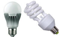
Once all the incandescent bulbs are gone, you’ll have to choose between LED and CFL.
Which to use, LED or CFL
Which is better, Compact Fluorescents (CFLs) or LEDs? I’m not the greenest person in the world and normally don’t go out of my way to be green, other than recycling trash.
Compact fluorescent
At one time legislation was going to cost you big time bucks if fluorescents, including CFLs, were broken. It was considered a “hazardous spill” and you had to open your windows; if you cleaned it up yourself you would not be able to use a vacuum or broom, only a sticky tape to clean it up. A professional team did this for a woman in Maine and after everything was done it cost her $3000.00 and insurance did not cover it. Now, it’s still not a good idea to use a vacuum because of the mercury.
Now all fluorescents are required to be recycled. Smaller recycle boxes can cost you as much as $1.50 a lamp to dispose. Some waste companies offer to be open on certain days and be available for you to bring the lamps to them. Today, with this legislation, nobody ever throws their light bulbs away (wink wink).
Light-emitting diode
LEDs are not cheap, but they are coming down in price. Right now the biggest change in LEDs is the lumens per watt, or the amount of light coming out divided by the wattage used. While the wattage on some lamps has not gone up, the light output has. It was just 2 years ago when the LED manufacturers started making lamps equal to a 75R30 (65BR30), which is the most popular residential light at the moment. Prices are starting to come down on older technology LEDs, and more and more stores are stocking them. LEDs contain no mercury, making them easy to dispose of, and no special handling, other than throwing them in the recycle bin. The energy saving is ridiculous! I just changed out 7 – 50 watt MR16 lamps with 7 – 6.2 watt dimmable lamps. That right there is a 87% energy savings, and it cuts out going up and down a ladder 56 times to change the lamps (7 lamps, 8 times). In this case, CFLs were not an option.
Now the negative about LEDs. When they first started becoming a reality in residential lighting they were advertised at 50,000 hours lamp life. Lawsuits happened, causing the big names in LEDs to start advertising 25,000 to 30,000 hours, with some lamps still rated at 50,000 hours. LEDs lose lumens over time, just like incandescent and CFLs, but LEDs lose more than 3 times that of a CFL: 29% to 9%.
So which should I use?
If you need beam control, LED has different beam spreads available, like floods, narrow floods, and spots. CFLs have none. LED and CFL fit medium sockets, like table lamps, but while some LED manufacturers do make LEDs to fit in fluorescent sockets, the price for residential use is almost prohibitive. If you have $3 you can buy a name brand CFL; if you have $25 you can buy some LEDs. Imports in each kind are cheaper. Just remember, whichever you choose, it is an investment, but there is most definitely a payback.
Tool Review: Ideal In-Sure™ Push-In Wire Connectors
A while ago I asked if push-in connectors were up to code. After determining they were, I checked the local Home Depot for these things every time I went. Then one day, bam! There they are. I grabbed an assorted 10 pack for ~$2.00, and ran home, filled with the type of excitement only a child feels on Christmas morning when he first lays eyes upon the bounty left by old Saint Nick. Admittedly, I was probably more excited than any grown man should ever be over this sort of thing.
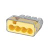
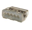
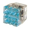
Some may not know what Ideal In-Sure™ Push-In Wire Connectors are used for. Ideal In-Sure™ Push-In Wire Connectors, are devices used for joining two or more wires and insulating those connections. They can be used as an alternative to traditional twist-on wire caps (wire nuts), and require no twisting motion to create a solid connection. When using push-in connectors, the ends of the wires to be joined are stripped and pushed into the connectors. With traditional wire caps, the wires would have to be twisted together (mechanically joined) before twisting on the insulating wire cap.
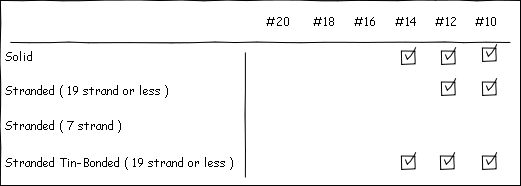
Unlike twist-on wire connectors, it’s easy to remember how many wires can be connected with a single push-in wire connector. If you have a 2-port connector, you can connect any combination of 2 #18 AWG to #12 AWG wires. Using twist-on connectors, you’ll likely have to memorize or reference a combination chart.
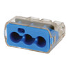
In-Sure™ Push-In Wire Connectors come in 7 varieties, so selecting the appropriate connector is easy.
2-Port
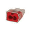
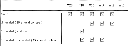
Acceptable Wire Sizes
3-Port
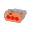
Acceptable Wire Sizes
3-Port Large
Acceptable Wire Sizes
4-Port
Acceptable Wire Sizes
5-Port

Acceptable Wire Sizes
6-Port
Acceptable Wire Sizes
8-Port

Acceptable Wire Sizes
Features
- No-twist connection reduces repetitive motion fatigue
- Low insertion force for fast and easy connections
- Compact size makes installation easy
- Clear shell gives visual verification of connection
- UL Listed to 486C and CSA Certified to C22.2 #188
- UL 467 Listed for grounding and bonding applications
- 600V maximum building wire, 1000V maximum signs and lighting fixtures
- Shell rated at 105 C (221 F)
Most old school electricians hate push connectors, due mostly to the crappy design of the first generation stab connectors on the back of receptacles. I, however, am more open minded, and will try anything that might make a job easier.
Once I got these things home, I did the only thing any reasonable and sane DIYer would do: I took one apart to see how they worked.
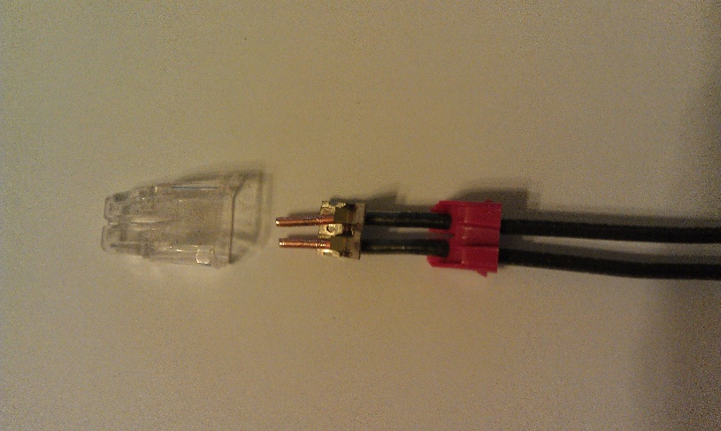
As you can see, they’re made up of three parts. The bushing (red), the contacts (metallic), and the insulating cover (clear).
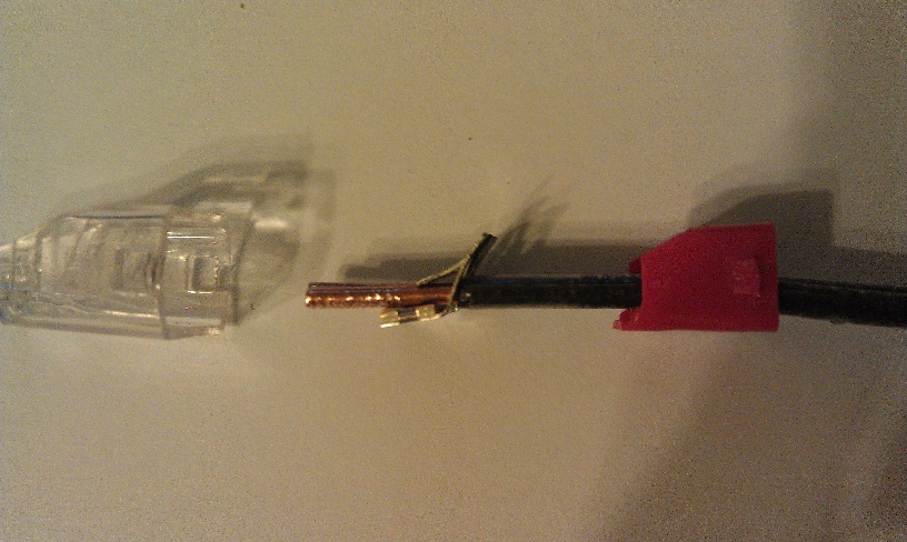
From the side, you can clearly see how the wires are held in place. And let me tell you, they are held in place really well. I yanked, tugged, pried, and pulled to try and get the wires to come out. So under normal circumstances, you shouldn’t have to worry about a wire slipping out. I did, however, find a way to remove the wires surprisingly easily. If you twist the wire back and forth while pulling, the wires will come right out. Doing so does damage the wire quite badly (you may be able to see the damage if you look closely at the above images), so it would have to be trimmed back and re-stripped before inserting it into a new connector. According to Ideal, twisting the wire to release it is a feature, not a bug.
When fully inserted into the connectors, the wires make a solid connection. So there should be no worry of resistive heating or arcing with these connectors.
Now I was satisfied the wires were not going to fall out, and I wasn’t going to burn down the house due to a bad connection. I decided to see how much time these things could save me in a typical situation. I wanted to see how long it would take to wire up a simple luminaire, first with traditional twist-on wire caps, then with push-in wire connectors.
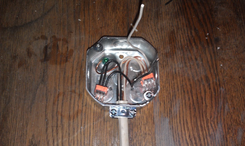
The Setup
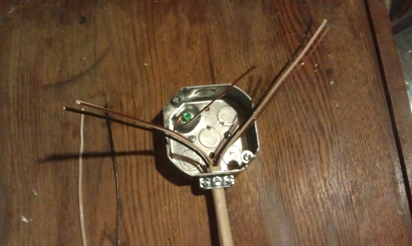
As you can see, I set up a typical scenario that electricians have seen many times. I have a feeder (from breaker), a feeder to the next fixture, and a couple pig-tails to connect the lamp holder.
Twist-on wire caps
The Procedure
- Strip wires.
- Twist wires together.
- Trim wires.
- Install wire cap.
- Repeat for each group of wires.
The Result
3:03.2
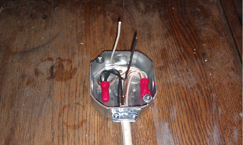
Push-in Wire Connectors
The Procedure
- Strip wires.
- Insert into wire cap.
The Result
1:50.5
For each luminaire I could save over a minute, using push-in wire connectors. That could be quite a time saver, if I was installing 10-20 lights.
The only fault I could find is that the wires can easily be twisted out of the connector. I don’t think this is a major issue; since the wiring would likely not see that much motion, but it is a small issue that hopefully Ideal can work out. They do cost more than the run of the mill twist-on wire cap, but the installation time savings could easily render that moot. All in all, I’d say these are a pretty slick product. I give Ideal In-Sure™ Push-In Wire Connectors 4 Captain Constructions out of 5.

Poles and Throws
No, we’re not talking Caber Toss here (I don’t have the legs for a skirt… err kilt… call it what you will, it’s still not a good idea to wear it while you’re working around the house).

We’re talking about switches! Specifically those found in your home, used to turn on and off lights and other devices.

First let’s start by defining a switch. A switch is a device for making and breaking the connection in an electric circuit. A switch can have one or many poles and one or many throws. All switches look about the same on the outside; a lever or button that is flipped or pushed, but internally the number of poles and throws determine how the switch is used.
In a switch, a Pole is the number of circuits that can be controlled by a switch. It might be easier to think of this as the number of inputs. Throws are the number of positions the switch can take. Throws can be thought of as the number of outputs (sort of).
Single Pole Single Throw (SPST)
A single pole single throw switch has one input, and one output. It is used to turn a circuit on, or off. “But wait…” you might be thinking “It turns the circuit on and off, isn’t that a double throw?“. You’re sort of right, I guess I didn’t explain throws so well. It’s not about the physical positions a switch can be in: up or down, it’s about the number of contacts in the switch. Maybe it’s easier to explain with a picture.

As you can see, there is one pole contact and one throw contact. With a SPST switch, turning on and off the light is easy.
Now that we’ve got the concept down, let’s take a look at some other types of switches. Keep in mind that you can have switches with as many poles and throws as you need, but we’re only going to focus on those typically found in residential wiring.
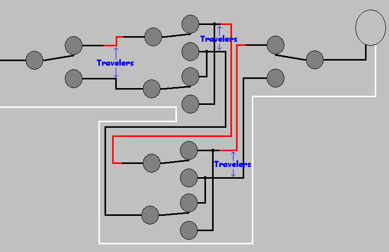
Single Pole Double Throw (SPDT)
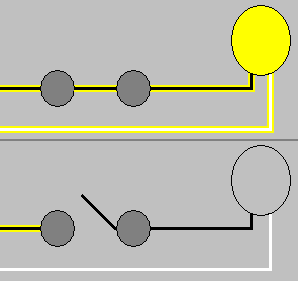
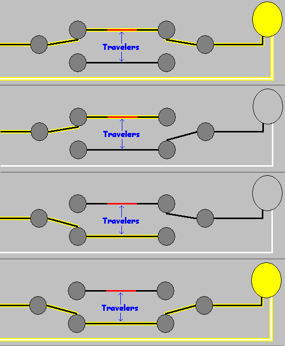
A single pole double throw may also be known as a 3-way (2-way in Europe) switch. They are used to control a single device (light, string of lights, etc) from multiple locations. With this kind of switch, you can turn the light on at the bottom of the stairs. Then you can walk up the stairs and turn the light off at the top of the stairs. To do this, you’ll need two SPDT switches. One switch at the top and one at the bottom of the stairs. Internally they look like this:
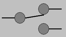
As you can see, the single circuit can be switched between one of two contacts. In the US, these two contacts will be connected using wires called Travelers. These wires connect the contacts of one SPDT switch to the contacts of another SPDT switch (typically).

So how does this turn the lights on and off? Well let’s finish the drawing.
The power from the circuit is connected to one of the switch’s pole contacts, and the light is connected to the other switch’s pole contact. When both switches are in a similar position, electricity flows in the first switch, through one of the traveler wires to the other switch, and finally to the light.
“What if I want to control a light from more than two locations?” you might ask. Well, that’s where the next switch comes in.
Double Pole Double Throw (DPDT)
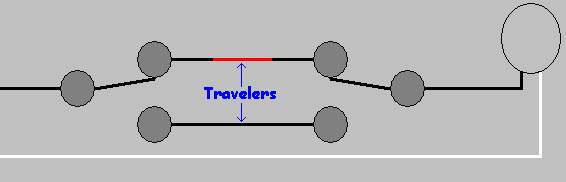
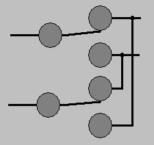
Double pole double throw, also known as 4-way or intermediate switches, allow you to connect as many switches as you’d like into the circuit. Internally they look like this:
To control the light, we’ll add them into the circuit on the travelers between our SPDT switches.
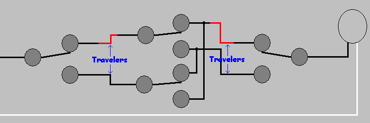
Now the current will flow into the first SPDT switch, out along one of the travelers to the DPDT switch, along one of the other travelers to the second SPDT switch, then finally to the light.
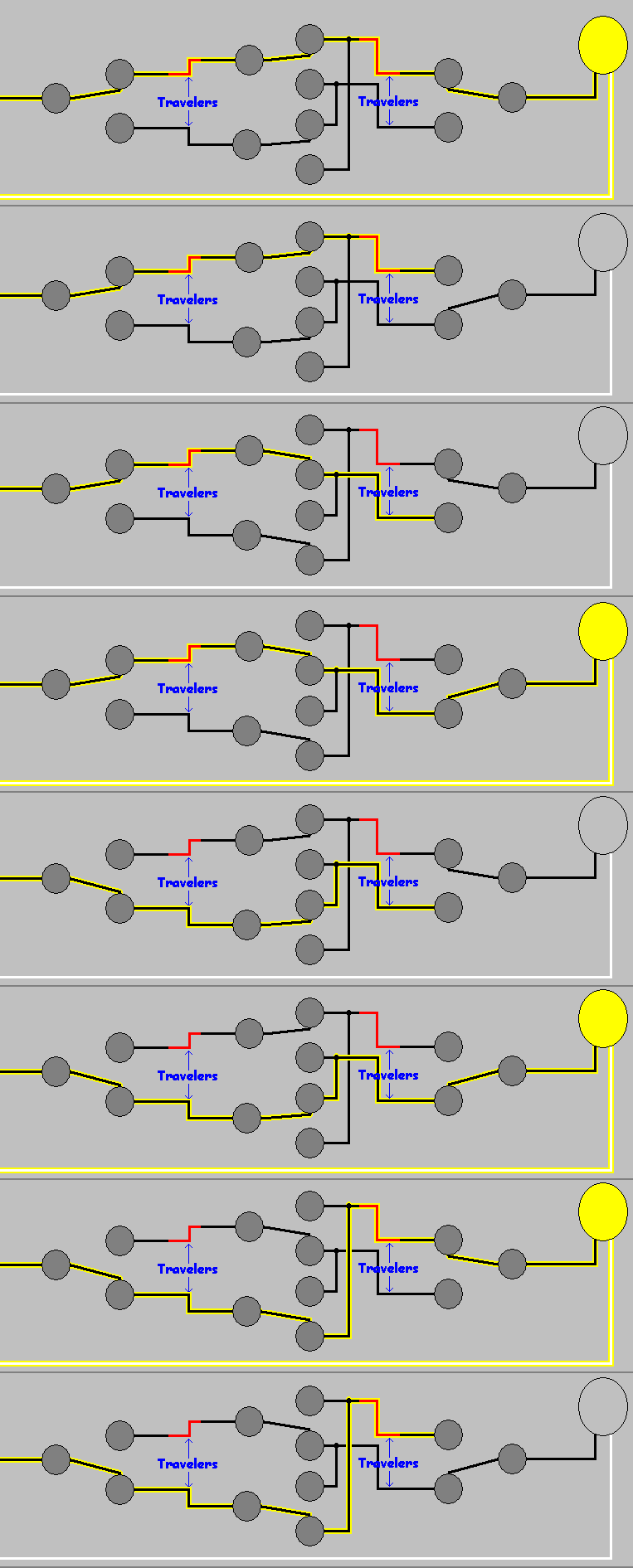
Using DPDT switches, we can control a device from as many locations as we want (within reason). All we have to do is add another DPDT switch, like so:
Understanding switches will help you whether you need to control a single light from one place or a group of lights from multiple locations. Anything you can imagine can be done, if you choose the right switch for the job. And please, no kilts while you’re working. It’s just dangerous.
Safer Than A One-Horse Open Sleigh
Electrical Safety
When preparing to put up holiday decorations, most people don’t think twice about plugging in all those twinkling lights. An open outlet just means room for more lights, an inflatable Santa, or dancing elves.
Then, you finish installing all the decorations, connect the final plug, and get 2 seconds of blinding Christmas glory followed by endless dark disappointment. You’re left standing in the snow holding the ends of two extension cords, mouth agape, wondering what just happened.
Well my friend, you know those things scattered around the house that look like this…?
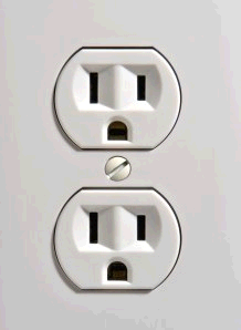
They have limits, rules, and even hidden dangers.
1440
When planning your holiday display (you do have a plan don’t you?), you have to consider more than just if Santa should be on the left of the gum drop forest or the right. You have to determine how much electricity you need, and how it will get to where you need it.
If you’re planning to power your display with a single receptacle, you’ll want to remember the number 1440. 1440 is 80% of the total wattage supplied by a 15Amp circuit, and the total wattage your decorations should use. Don’t believe me? Lets do some math…
First, the typical residential receptacle (in the United States) is on a 15 Ampere circuit at 120 Volts. So…
15A * 120V = 1800 Watts
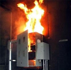
This is the total wattage that can be used, before bad things start to happen. (Think evil fire demons.) So, to be safe, we’ll stay below 80% of the total wattage.
1800 * 0.80 = 1440 watts
See, told you I didn’t make it up.
“So I can hook up 1,440 watts of decorations!?”.
Hold on a second there, Jack. Remember I said “the typical residential receptacle is on a 15 Ampere circuit“? Well, it’s not likely it’s the only receptacle on the circuit. So to determine how much power you have for your decorations, you’ll have to figure out how much power other stuff is using.
The first thing you’ll have to do is find out what else is on the circuit. You might get lucky and it will be written on the door of the service panel. (For those unfamiliar, that’s the big metal box with all the big, funny switches.) If not, then the easiest way to find out is to turn the breaker off and see what stops working.
Now that you know what else is on the circuit, you’ll have to determine how much power is being used. Light bulbs are easy; they have the wattage printed right on them. For other things, there should be a label on the cord or near where the cord enters the device. Wait… What? You took the label off? Why would you do that? No matter, you should be able to estimate the usage with a chart like this Power Consumption Table.
Or you can use an ammeter to measure the actual usage.

To use an ammeter, simply clamp it around the hot wire leading to the device. If you clamp it around both wires, you’ll read 0. (Or at least you better measure 0, otherwise you have a problem). This will tell you how many Amperes the device is drawing, which can be used to determine wattage thanks to Georg Ohm. Here we go with math again…
Ohm found that Current (Amperes) * Voltage = Watts. He even made this cool wheel thing to help us out. (Maybe he didn’t draw it himself. How should I know? I’m not Wikipedia.)
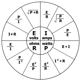
You can use this formula to figure out how many watts a device will use.
<device amps> * 120 volts = watts
Now that we know how much power is being used by other things on the circuit, we can figure out how much Christmas cheer we can plug in.
Simply subtract the total of all the devices from 1440.
1440 – <total wattage of other devices> = Remaining holiday joy.
Any Christmas decoration that consumes power, should have it’s power consumption listed on the box and/or the product itself. All you have to do is total up the consumption of the devices you want to use and subtract that from the remaining available wattage. This might be the hardest part, as you may have to decide which decorations are most important.
If you want to be able to connect more decorations, you could consider having a dedicated “seasonal” circuit installed. (You’ll need an electrician, and an empty space in the service panel for this.) I actually just did this myself.
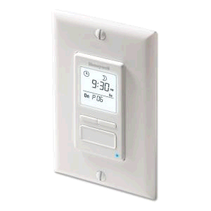
I installed a GFCI receptacle outside, in a weatherproof box (in the soffit of my porch). I decided to hook up to a 7 day programmable timer switch (for lights and motors), so I could control when the lights go on/off without having to remember to flip a switch (thanks to this question asked on DIY.StackExchange.com).
I had a new 15 Amp breaker installed in the service panel, and hooked the switch up to it.
Safely Connecting Santa
Now that we know how much stuff we can plug in, we have to be concerned with how we plug it in. To protect yourself and others from electric shock, all exterior Christmas decorations should be connected to a GFCI (Ground Fault Circuit Interuption) device. The GFCI will detect dangerous shock hazard situations, and turn the power off automatically.
Ground fault protection
If you have your decorations plugged into a standard receptacle, you can upgrade the receptacle to a GFCI receptacle.
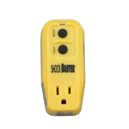
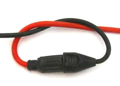
If you are using a lamp socket to outlet type adapter, you could use a Plug in GFCI device.
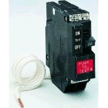
Another option, is to have the breaker replaced (by an electrician) with a GFCI breaker. This option provides protection to the entire circuit.
Extension cord safety
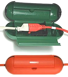
If you are using extension cords to power decorations, there are Waterproof extension cord covers available, that will make junctions water tight, and prevent the cords from easily coming unplugged.
If you have extension cords running across paths, where people will be walking, then you’ll want to cover the cord to protect it from physical damage and to prevent a possible trip hazard. It’s also a good idea to mark where the cord enters the path, and where it leaves it with flags. If snow falls and covers the cord, you don’t want to hit the cord with the snow blower. (While it may entertain your neighbors, it won’t be much fun for you.)
Wherever you have cord junctions (cords plugged into cords), you should take steps to prevent the junction from coming apart. This could be as simple as tying the cords together…
…or using a weatherproof device (see above), or physically attaching the cords to a structure using cable staples.
For more information on extension cord safety.
Protection at the plug
If cords are going to be plugged into a receptacle that is exposed to weather for an extended period of time, then you’ll want to get a outlet cover that is weatherproof, even when things are plugged in.

Summary
- Don’t use too much power.
- Protect yourself from ground faults.
- Run extension cords safely.
- Keep all electrical connections weatherproof.
Now that our plan is made. We know where everything will go, how it will connect, and where all the cords are. It’s time to get up on the ladder, and start hanging lights.
Ladder Safety
If you are using a ladder to hang holiday decorations, it’s important to follow a few safety precautions. Using a ladder unsafely could mean you’ll be spending the holidays on crutches or in a hospital bed.
Setting up the ladder
Height
The height of the ladder is the first point of concern. You want to make sure the ladder is tall enough so you can reach the work area comforatably, but not too tall that you won’t be able to position the ladder at a safe angle (discussed later). If you are going to be climbing onto the roof, you’ll want to make sure the ladder is long enough to reach at least 3 rungs (~36″) above the roof edge.
Stability
Make sure you place the ladder on a flat level surface, to prevent a tipping hazard. If you cannot find a level surface, you may be able to attach a ladder leveling product.

To make the ladder more stable, you can also purchase a ladder stabilizer.

These will not only make the ladder more stable, but also allow you to position the ladder against the house without crushing or damaging the gutters.
Angle
When positioning the ladder, you’ll want to make sure it’s at a 75° – 78° angle. The easiest way to determine if the ladder is at the proper angle is to stand with your toes against the bottom of the rails, then extend your arms strait out at shoulder height.

If your hands rest on a rung, your ladder is at a good working angle. If you can’t reach the rung, the ladder is at to shallow of an angle and you risk the bottom sliding out leading to a fall. If the rung is at your wrist or higher on your arm, the ladder is at too steep of an angle and you risk tipping backwards on the ladder.
Loads
Before stepping foot on the ladder, you want to make sure it is rated to hold your weight and the weight of any tools you may be carrying.
Working on the ladder
When working on the ladder you never, ever, want to overreach. Make sure you keep your torso between the rails at all times while working. If you can’t reach something, climb down, and reposition the ladder. It might be a little extra work, but it could save a trip to the emergency room.
If you are going to be getting on the roof, make sure the ladder extends at least 3 rungs above the roof edge. Always step onto the roof from a rung that is below the roof edge, and don’t ever step on a rung that is above the roof edge.
When working on ladders, it’s always good to have a partner, somebody to hold the ladder as you climb up/down. It’s also nice to have somebody around to set the ladder back up, if it happens to fall while you’re on the roof.
When climbing up/down the ladder, keep your hands free. Don’t climb the ladder with a hand full of tools; use a tool belt to keep your hand free.
For more information on ladder safety check out DIY.StackExchange How do I use an extension ladder to get onto my roof?, and visit Ladder Safety.org.
So! We safetly installed just the right amount of decorations without falling off the ladder, but how much will this awesome light display cost?
Calculating the cost of power consumption is fairly simple, especially since we’ve already determined how much power all the decorations use.
First we’ll start by figuring out how many kilowatts (kW) we are using, by dividing the wattage calculations from earlier by 1000 (1kW = 1000W).
<total wattage>/1000 = Total kW
Since the electric company charges by kilowatt hours (kWh), we’ll have to decide how many hours a day we’ll have the lights on. Then we simply multiply our kW calculation by the number of hours we have the light on.
kW * hours = kWh
Next we’re going to have to go looking for an old electric bill, so we can figure out how much the electric company charges per kilowatt hour (I’ll use the national average at the time of writing for examples below). If we multiply our kWh total from above by the $/kWh the utility charges, we’ll know how much it costs to run the lights for one day.
kWh * $/kWh = $ per day
Now that we know how much it costs for one day, we can simply multiply that by the number of days we’ll have the lights on.
$/day * days = Total cost
Lets figure out some examples, just to give you an idea of how much typical decorations can cost (calculations assume 8 hours per day, for 30 days).
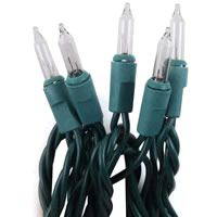 Incandescent mini string lights (50) = 20.4 Watts
20.4W / 1000 = 0.0204kW
8 hours * 30 days = 240 hours
0.0204kW * 240h = 4.896kWh
4.896kWh * $0.10 = $0.4896
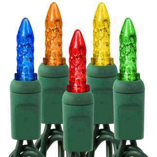 LED mini string lights (70) = 4.8 watts
4.8 / 1000 = 0.0048kW
8 hours * 30 days = 240 hours
0.0048kW * 240h = 1.152kWh
1.152kWh * $0.10 = $0.1152
 Oh yeah, we can’t forget the 12′ inflatable Santa Clause = 78 watts
78 / 1000 = 0.078kW
8 hours * 30 days = 240 hours 0.078kW * 240h = 18.72 kWh
18.72 kWh * $0.10 = $1.872
Just for fun, lets see how much it would cost if we maxed out our circuit.
1440 / 1000 = 1.44kW
8 hours * 30 days = 240 hours
1.44kW * 240h = 345.6kWh
345.6kWh * $0.10 = $34.56
Now that we’ve learned how to be safe while decorating for the holidays, the only thing left to do is enjoy the season.
Happy Holidays from all of us at DIY.StackExchange.com, and The DIY.SE blog team

Home Improvement Blog on Google+
Home Improvement Blog on FaceBook
Bloggers Wanted
Latest Articles
Topics
- Electrical (8)
- Introductions (7)
- Plumbing (3)
- Projects (13)
- Repair (4)
- Safety (5)
- Tips and Tricks (5)
- Tool Review (5)
- Tools (6)
- Uncategorized (5)