Archive for July, 2013
Demystifying the mystifying GFCI
A commonly misunderstood electrical device, is the Ground-Fault Circuit Interrupter (GFCI). Whether posing as a circuit breaker, or a receptacle, the GFCI device is almost always misunderstood. To understand the GFCI, however, you have to know a bit (and I mean a really little bit) about transformers.
This is a transformer.
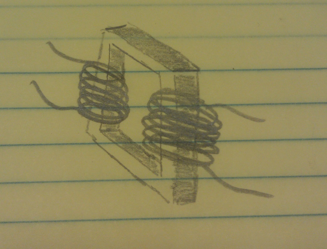
(Well, a crude representation of one anyway). It consists of an iron core, and a couple coils of wires.
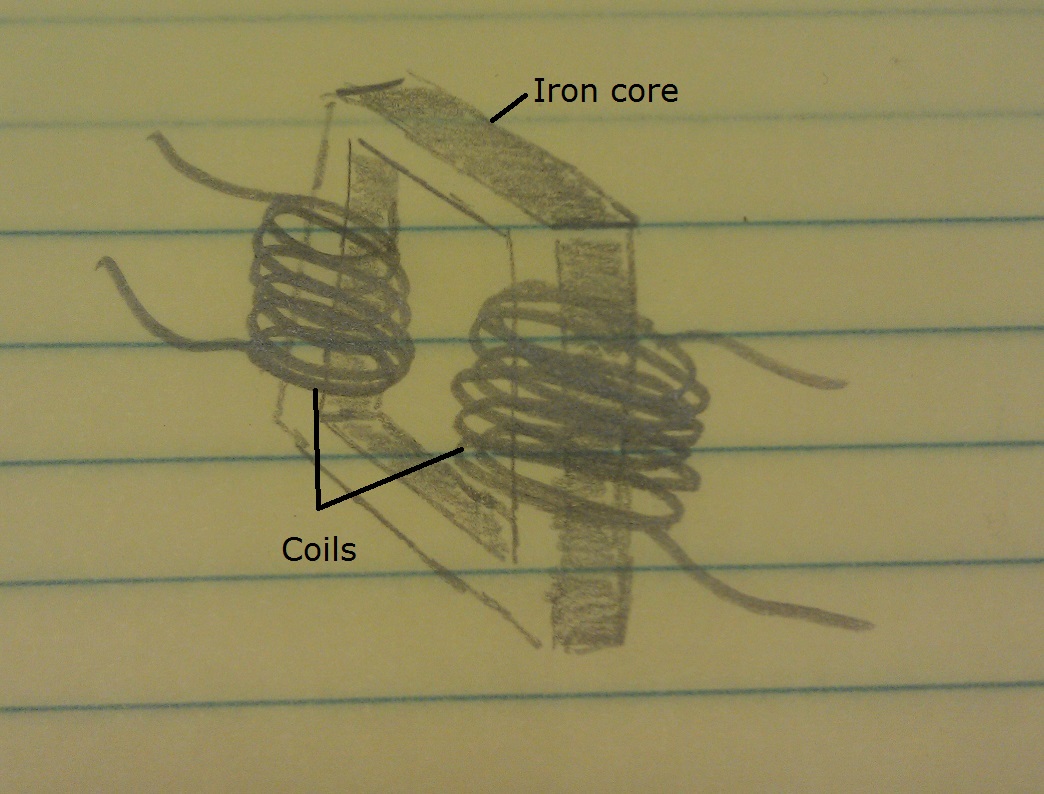
More specifically, it has a primary coil of wire, and a secondary coil of wire.

When you place a voltage on the primary coil, some magnetic magic happens in the core and a voltage is induced on the secondary coil.

And there you have the most basic crash course, on the most coarse basics of transformers. Which is all you need, to understand how GFCI devices work.
Inside a GFCI device, you’ll find what’s called a Current Transformer (CT). A crude representation of a CT, looks something like this.
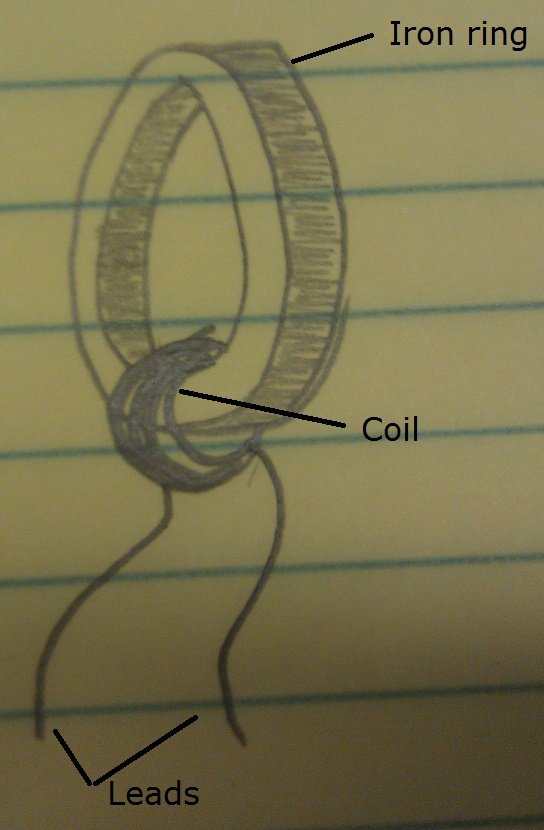
A CT works just like any other transformer. When a voltage is applied to the primary, a voltage is induced on the secondary. The only difference, is that the primary isn’t a coil, exactly. The primary is instead the ungrounded (hot), and grounded (neutral) conductors of an electrical circuit.
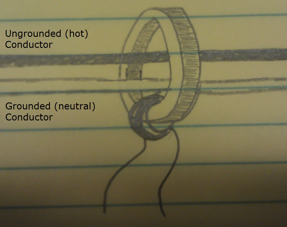
When current is drawn on the circuit, it flows down the ungrounded (hot) cunductor. Out to the consuming device, then returns back to the source on the grounded (neutral) conductor. Similarly, if we draw current from a GFCI device. It flows down through the ungrounded (hot) conductor, and through the CT core.
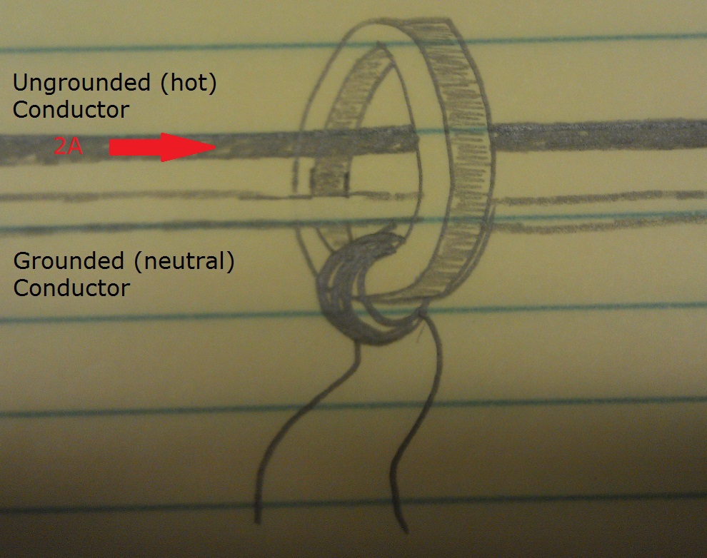
The current then flows back through the CT on the grounded (neutral) conductor, and back to the source.

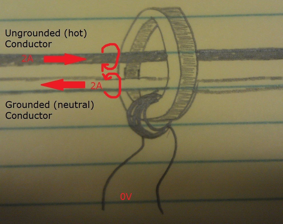
According to the right hand rule. If you point the thumb of your right hand in the direction of current flow, and wrap your fingers around the conductor, your fingers point in the direction of the magnetic field produced by the flowing current. If this is done with the above diagram, we end up with magnetic field lines like this.

Because of the proximity, and opposite-ness of the fields. They cancel each other out, and no voltage is induced on the secondary coil of the CT.
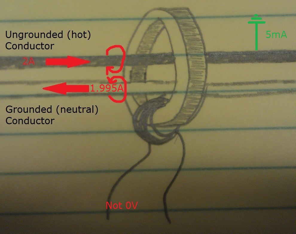
In the case of a ground-fault, however, not all the current will flow back along the grounded (neutral) conductor. This creates an imbalance in the magnetic fields, which allows magnetic magic to occur in the transformer core, and a voltage is induced on the secondary of the CT. If the voltage on the CT is large enough, and lasts long enough, the GFCI device will open the circuit.
Next time you come across a GFCI device that continually trips, think about how it works and what it’s looking for. This might give you a better idea of what to look for, and where to start troubleshooting. And remember to always work safely, and cautiously whenever you’re working with electricity.

Home Improvement Blog on Google+
Home Improvement Blog on FaceBook
Bloggers Wanted
Latest Articles
Topics
- Electrical (8)
- Introductions (7)
- Plumbing (3)
- Projects (13)
- Repair (4)
- Safety (5)
- Tips and Tricks (5)
- Tool Review (5)
- Tools (6)
- Uncategorized (5)