Archive for July, 2014
Kitchen Renovation – Moving to Open Concept
This is part two of a series.
For part one, read Kitchen Renovation – Introduction and Footings.
The previous installment dealt with the building a new footing to support the interior end of the beam. When I last left you, I had posted a picture of wet concrete in a hole. As luck would have it, that wet concrete soon became dry, hard concrete. I watered it a couple of times to help it cure, and waited the prescribed 5 days (warm weather) curing time before loading it. Installing the posts was relatively simple. Cut 2x4s to length, hammer them into the bracket, and bolt them together. Well, it should have been simple. The problem was that 5 2x4s makes a post 7 1/2 inches. I had a stud that I really didn’t want to demolish at about 16 inches on either side. My drill, with a bit long enough to penetrate the post, was just too big to fit in that stud bay. The idea occurred to me that I could use a shorter bit, and by drilling the holes with absolute perfection, have them meet somewhere in the middle. However, that involves more precision than I am capable of; so I nixed that idea right off the bat. I ended up using a short, 3/8 spade bit to start the hole, and when I had gone in a couple of inches, stuck the long bit in the hole, wiggled my drill onto the long bit, and using some severe bodily contortions, managed to tighten the chuck. Then I finished drilling.
Now that the holes were drilled, it should have been a simple matter of slipping the bolts in and tightening the nuts. Not quite. There was a new problem. An 8-inch carriage bolt doesn’t quite make it through 7 1/2 inches of post when the 2x4s aren’t exactly tight together. I grabbed a couple of bar clamps and tried to move everything, but it just didn’t work. Road Trip! Off to the the blue store! At the blue store, I bought a ten inch bolt. I stuck it in, and nutted it tight, and everything came together tightly — tight enough that the next hole now took the 8 inch. Working up, I pulled the post together, and when I was done, took the ten-incher out and replaced it with and 8. I’m sure I could have returned the long bolt, but I had used it, and decided not to.
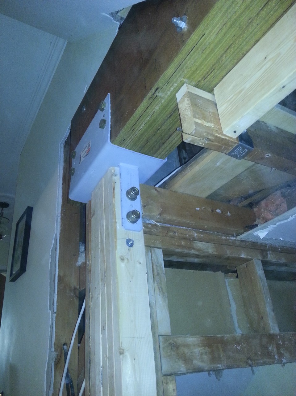
I installed a bit of blocking at the top, used structural screws to the header, and 10d nails into the bracket at the bottom. Once everything was done, it felt really solid. I’m not a structural engineer, but sometimes you can just tell that something won’t fall down. This won’t. Unfortunately, I was rather neglectful in the camera department, so all I have is a picture of the top of the post.
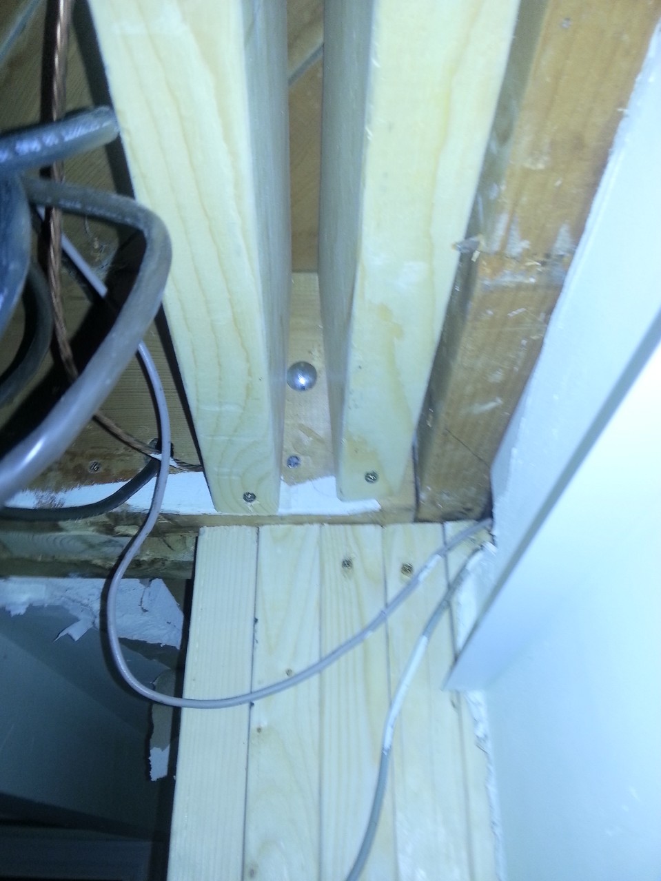
Top of basement post.
Next Step: Prepare for the post at the other end.
This one should have been simpler. I had a lot more room to work, having cleared out a couple feet of plaster on either side. The plan called for a single 8″ bracket, drilled into and epoxied to the top of the foundation wall. I had a sneaking suspicion that the foundation wall might have been hollow block, which would have required me to fill a couple of courses with concrete before mounting the bracket. Luckily, I was wrong. It was a solid poured foundation and it was wide enough for full bearing. Simple! All I need to do is drill and slip in my bracket. What I didn’t consider, and neither did my engineer, was that all those joists had to end up somewhere. In particular, the 2×8 double joist that was supporting the existing wall would probably be resting on the foundation wall right where I wanted to put my post! There was a third joist a couple inches away, and the space between was filled another bit of 2×8. So I opened up my finest drafting tool (MSPaint) and put together a quick sketch to email to the engineer:
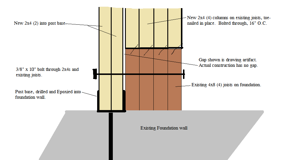
Revised plan for exterior wall post.
That email was sent off, and my wife and I went out to a friends for 1 pound striploins, many kilos of wine and several of Fidel’s finest exports. The engineer got back the next day and approved my revision. Road Trip! This time, to the orange store, which rents tools. I rented a concrete drill and bought a tube of concrete epoxy. It took about 3 minutes out of a 4 hour rental to drill the hole. I cleaned the hole out with the shop vac, squeezed in the tube of epoxy, and stuck the base in. I quit there, figuring we’d put the post up on beam day. Besides, I had a whole lot more work to do.
Demolition:
Once again we enter the realm of lower skilled labour. My contractor is booked solid over the summer, and can only give me a day here and there for jobs that I really need him for. Swinging a hammer at old plaster walls isn’t a valuable use of his skills. So I did it myself. First, I put 6 mil poly and duct tape over every door in the house. I had learned from the small amount of demolition that I had already done for the front post, that dust gets everywhere. Turns out I needn’t have bothered. Dust got everywhere anyways. I did have the foresight to put big shipping bags over all the furniture that was too big to move out, and laid the 6-mil over the wood floor. Then I spent two days swinging a sledge, prying and reciprocating away the plaster walls. Not fun work, but also not work I want to pay top dollar for. A second person would have been useful to make trips to the dumpster, but I didn’t want my spouse becoming concerned over the mess I was creating. The only point of interest is that plaster is messy, and some genius thought it would be a brilliant idea to put wire mesh on ever corner, both inside and outside, nailed about every 2 inches. I suppose it was meant to last, and it did last for 50 years, but I wanted it to no longer last. I also ran into something the previous owner had done himself. At one point he had installed some off the shelf cabinetry, and added a couple more cabinets than the original builder had. This meant that the bulkheads didn’t quite match up. So he boxed them out with plywood. The only problem was that he was a frugal man. The type of penny-pinching gentleman that saves every screw he has ever removed in a jar. Well, he used those recycled treasures on this project. It took five different screwdrivers to pull them out: two sizes of Phillips, red and green Robertson and a slot. I saved those screws, and will use them to install something just before I sell the house. He actually did a good job of it. Everything was tight and square, and there was no room to squeeze in my reciprocating saw with a metal blade to cut them off.
At some point in there, my brother-in-law and his wife came over to help Anna pack up the cabinetry, and destroy any cabinetry that we could get away without. I also made some trips to the specialty lumber yard to order parts. I needed a couple of big nasty metal brackets to connect the beam to the posts. The load should be bearing down on the posts vertically, but we need something that can handle a bit of torque or the whole house collapses like this: / /. I also needed to order the beam, which was 4 plies of 16 inch by 1 3/4 inch LVL. The parts I needed, while standard in the catalogue, are actually made to order. This meant some delays, but the Simpson Strong Tie plant is only a 15 minute drive from my place, so I saved some time by picking them up rather than waiting for delivery. I also went to the bolt specialty store to pick up big 3/4 inch by 8 inch bolts at 8 bucks a piece.
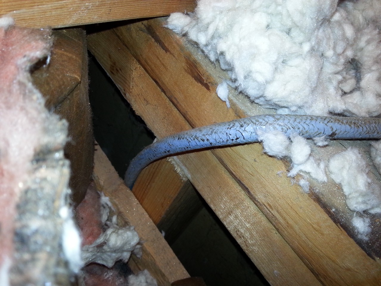
Also somewhere in there, I spent a day and a half moving electrical circuits away from the wall to be demolished. Unfortunately, the orange store did not have wire stretchers available for rent, so it involved purchasing junction boxes to put in the basement drop ceiling or attic for splicing purposes. Only three orange/blue trips. Managed to snag a 20 m roll of 14/2 off of my next door neighbour who literally just happened to be carrying it out of the house to my bin (with my permission), as she was cleaning up her late husbands workbench. The fun work begins:
Wiht all the prep done, it’s now that most joyous of days! Beam Day! My contractor, Adriano and his buddy Franky showed up, with a truckload of tools, when they said they would, with a cup of Tim Horton’s each. On time and pre-coffeed. These are responsible contractors. They took 15 minutes to look at my plans, look at my parts, and took off to the orange store to buy big honking drill bits. Half an hour later, they were back, ready to work.
The first thing we did was install the post at the front, and mount one of the big ECC brackets. Then more of the same at the other end. IMPORTANT: Everything takes longer than you expect. Cutting, drilling and bolting 5 2x4s together should only take 10 minutes. Wrong. It’s more like 30. Then drill 2 8-inch by 3/4 inch holes for the bracket bolts. About 15 minutes each. Between Adriano’s drill, Franky’s drill and my drill, we managed to not heat them up too much. Adriano did one end, Franky the other, and I ran around and did what I was told without getting in the way. Once the post and brackets were up, it was time to install the beam.
We live in a back split, and are very fortunate (for this job) to have fantastic access to the the attic. Through the wall — not the ceiling. But, even with that, there was no way we were going to be able to manouevre a 23-foot long beam to that access door. Particularly since we only had 20 feet to the back of the house. Adriano went into the kids’ room, and took out a window. Something I never would have had the courage to do. (For fear of breaking the glass or slicing my hand off.) Franky and Adriano fed the beam segments up to the second floor window, while I grabbed and got it into the house to a balance point. Then I could hold it while the guys ran upstairs to feed it in the rest of the way. The first three segments went in easily, the fourth required a bit of “encouragement”. But we squeezed them into the brackets. We now had 4 plies in the brackets — and it was only 10:30. This job would be done by noon! Franky screwed a 2×6 across the joists parallel to the beam so we could use a pry-bar to straighten the beam, and temporarily screw it the the joists to keep it straight. (Important: do this before bolting to the brackets.)
All that was left was to drill 8 3/4 inch holes, 24 1/2 inch holes, bolt everything in, and nail up the joist hangers. That took another 4 hours. Plus a trip to the blue store for more nuts and nails. At 2:30, it was time to test our creation. Franky and Adriano went at the stud wall with sledges and pry-bars and got rid of the of the offending lumber while I ran back and forth to the dumpster. At 3:15, there was a mass rush with brooms, garbage cans and the shop vac, while we fought over the ownership of tools. Actually, sorting out tools was easy. I had designated 3 areas beforehand so that each person had their own storage. Other than a couple of drill and impact bits that we were exchanging freely, everyone respected the zones.
3:45, beer on the back patio, while I counted money out to the boys. They earned every penny. There was no way I could have done this job with a couple of unskilled buddies and a case of beer.
The Money Shot!
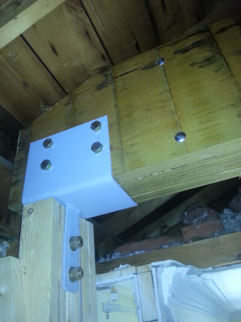
Post and Beam connection against exterior wall.
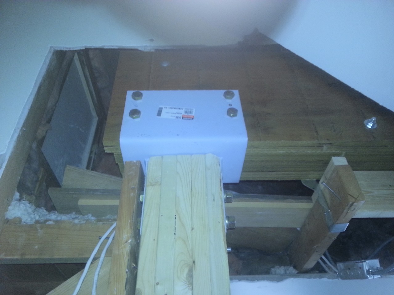
Post and Beam – Interior
Post and Beam Interior
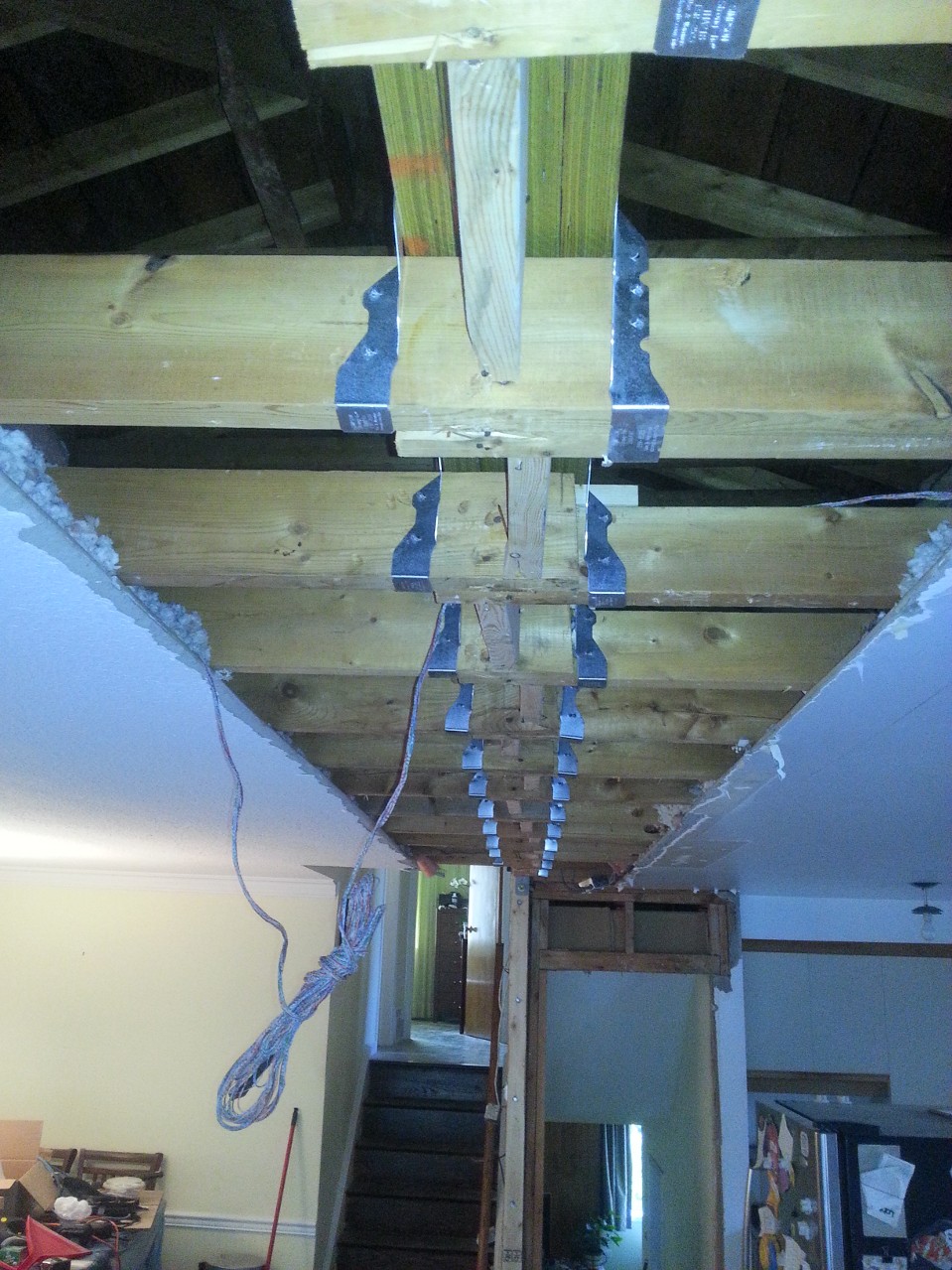
Joist hangers
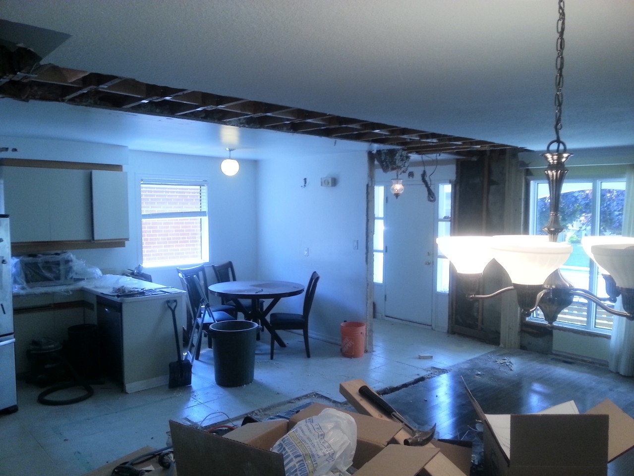
Why we did this
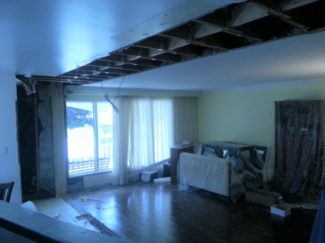
Reverse angle
Anna was thrilled when she came home. We had finally achieved the open concept that we wanted. Well worth the effort.
The question I know you all have is “Was he properly attired during all this work?” I’ll leave you with this photo, salt stains and all:

Next Up: Flooring, Kitchen and more demo.

Kitchen Renovation – Introduction and Footings.
Lifestyles have changed. In a 1950s Leave It to Beaver world, urban people had very clearly defined roles. Dad would entertain the guests while Mom hid in the kitchen preparing a meal. Design reflected that. Kitchens were viewed as utilitarian areas in which guest were not to enter.
1960s and 70s design at least acknowledged that families would often eat in the kitchen, and more space was provided to accommodate a kitchen table.
Some time in the 80s and 90s the kitchen evolved into a more public space. Guests would gather and even help out in the preparation of a meal. The drawback was that seating was often uncomfortable.
More recently, the trend has been to open concept kitchens. This design philosophy often puts the kitchen right next to a dining/living room without a wall separating them. It allows the guests to sit comfortably on a couch, have drinks and snacks on the coffee table while still allowing interaction with the people in the kitchen working on the meal. It fits in with a more modern lifestyle.
Our house was built in the 60s. We have a 20′ x 10′ kitchen separated from the living/dining room (24′ x 14′) with a central supporting wall. We finally decided that that wall has to go.

One end of the wall to destroy
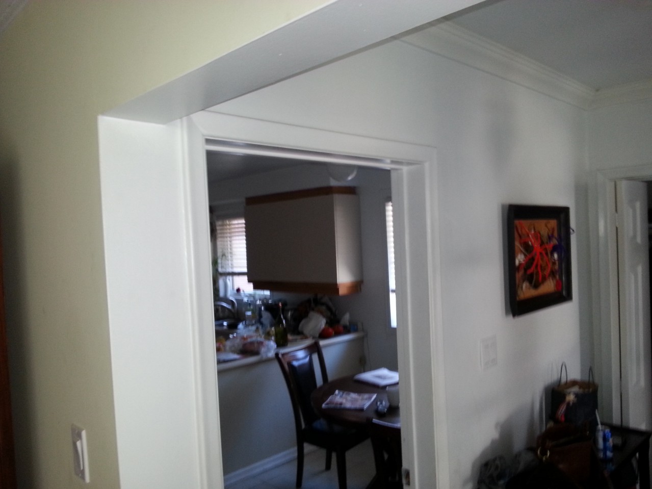
The other end, with a glimpse of our lovely 80s cabinetry
Also on the list is updating our extremely dated cabinetry, which had been installed by the previous owner, probably from off the shelf cabinets. Hinges are going, finish is chipped. The laminate counter-top is swelling up in the humidity making it nearly impossible to open some of the drawers. Corner Cabinets require me to change into my spelunking equipment in order to find anything. We need an update.
So, the plan is:
- Remove dividing wall.
- Re-tile the floor.
- Replace the cabinetry.
- Re-wire so that we can make coffee and dry our hair at the same time. (Bath and Kitchen are on the same breaker)
- Install a fume hood (requires moving the stove) from an internal to an external wall.
- While the cabinets are gone, stud out the uninsulated exterior wall and put some pink stuff in there.
- Do a fantastic job, as cheaply as possible. Hire experts where needed, DIY where we (I) can.
We shopped out the cabinetry and designed the new kitchen ourselves. Next step. Call an engineer to figure out how to get rid of that wall.
Fortunately, the wall isn’t carrying a heavy structural load, but the ceiling joists are lapped on top of the wall, and they support the ceiling plaster, insulation above, and any light fixtures. So we can’t just knock down the wall, or the ceiling will collapse into the center of the house.
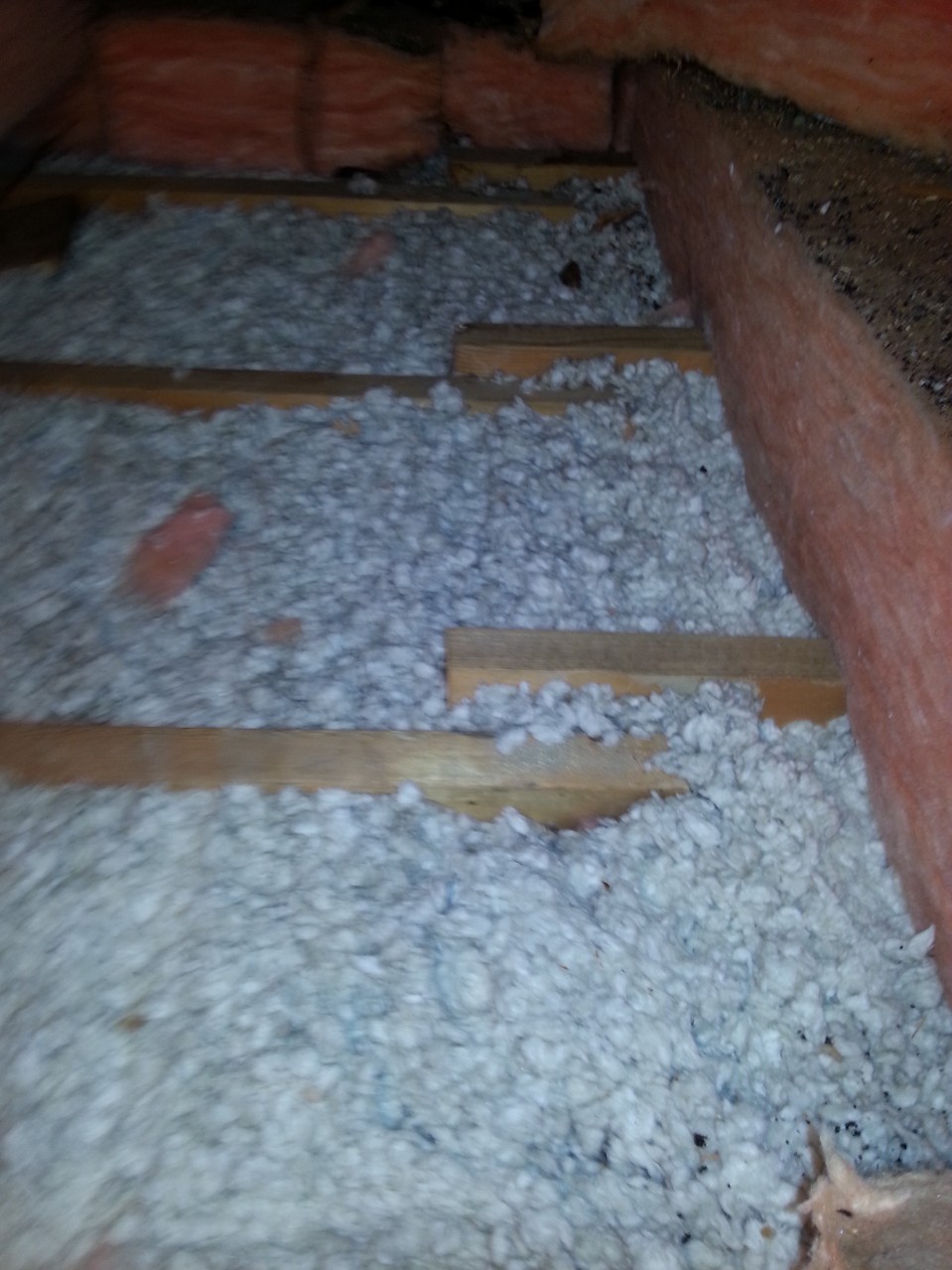
Lapped ceiling joists…
On top of this stud wall
The solution is to install a beam to take the load off the wall, and then knock down the wall. The problem is that the existing stud wall carries a linearly distributed load. A beam, being supported at the ends only, will put the load onto two points. Consequently, these loads need to be tied into the foundation.
Step 1: Footing.
The post at the front of the house is relatively easy. It will rest on the foundation wall, which is (I assume), hollow construction blocks. I’ll simply need to fill them with concrete, a couple of blocks deep, and stick in some column base connectors while the concrete is still wet.
It’s the other end that’s the problem. I need to dig a new footing. The engineer specified a footing of 22″ x 26″ by 14″ inches deep, with a 15 mm @ 4″ spacing rebar grid, 2.5″ below the surface.
Now, digging is traditionally used as an example of extremely unskilled labour. “But the world needs ditch diggers too!” is often used as a rallying cry against sending everyone to university. Unskilled labour? I’m highly skilled at unskilled labour. This is right up my alley, and a job I can save money on.
So I started digging. This isn’t as easy as you think, because the floor is concrete. I made several false starts. I tried drilling holes with a masonry bit to create some break lines. It worked somewhat but was tediously slow.
Next I took out a mason’s hammer, with a pick on one end and just started whacking away at the center of the field. It was slow and tedious, but eventually I managed to break away a hole big enough for my hand. It was about 3 inches thick. Certainly not enough to support a load. I dug out some of the gravel underneath, and managed to whack away with a small sledge. Eventually, with a combination of under-digging and sledging, I got a rough opening dug. Then I used a sledge and chisel to clean up the edges. Concrete went into plastic pails, and were carried upstairs to the dumpster.
Digging out was much more difficult than I had imagined. I’m sitting on top of some of the hardest clay imaginable. In the end, I resorted to picking at it with the pointed end of the mason’s hammer, and scraping of 1″ thick layers with a hand trowel. Soon I ran into a problem. There was an old footing in my way.
Evil Old footing that is both useless and in the way.
This was 5″ thick, no where near enough for my engineer’s needs and just too thick for me to hack away with with the sledge or mason’s pick. Time for a trip to the rental store. I picked up a handheld demolition hammer (mini-electric-jackhammer) and went nuts on the concrete.
It also did a trick on the clay, allowing me to shovel it out rather than troweling it. Things went mighty smoothly. Fortunately, I had a nagging suspicion that there might be a clay sewer pipe in there somewhere. The last thing I wanted to do was crack it, so I went very carefully, probing with a thin rod, and hand digging around anything solid I found.
There was a clay pipe, and it was in the corner by the hammer head, about 12 inches from the surface. I did not break it. Infantry mine sweeping training comes in handy sometimes.
Next, I lined the hole with 6 mil poly, and threw an inch of gravel on top of that.
Meanwhile, my metal-working buddy was building the rebar for me. The main problem was that the engineer specified 15 mm bar, which is impossible to bend. 10 mm, I could have stuck in a vise, but 15 mm is just too much. He bent it in his massive hydraulic brake.
The rebar cage was made with 10″ legs, as per design. However the design also specified that the top of the cage should be 2.5″ from the surface. When I stuck it in the hole, It ended up 5 inches too low. In order to solve this problem, I ran a couple sticks of scrap lumber across the hole, and suspended it from them with mechanics wire. Good plan, as it allowed me to finely adjust the height.
Some time earlier, I put the call in to the inspector. In my jurisdiction (Toronto) All holes must be inspected by a city employed hole inspector before you make them not a hole anymore. This is actually a good idea. The building department’s job is to verify that you are following the plan. The only way they can tell, is if they see the hole as a hole. If it’s full of concrete, they have no way of knowing whether it is the proper depth, or if the rebar is even there.
Shortly after I wired the rebar in, the inspector showed up, looked at my plans, said “Yup, It’s a hole. You’re good to pour.”
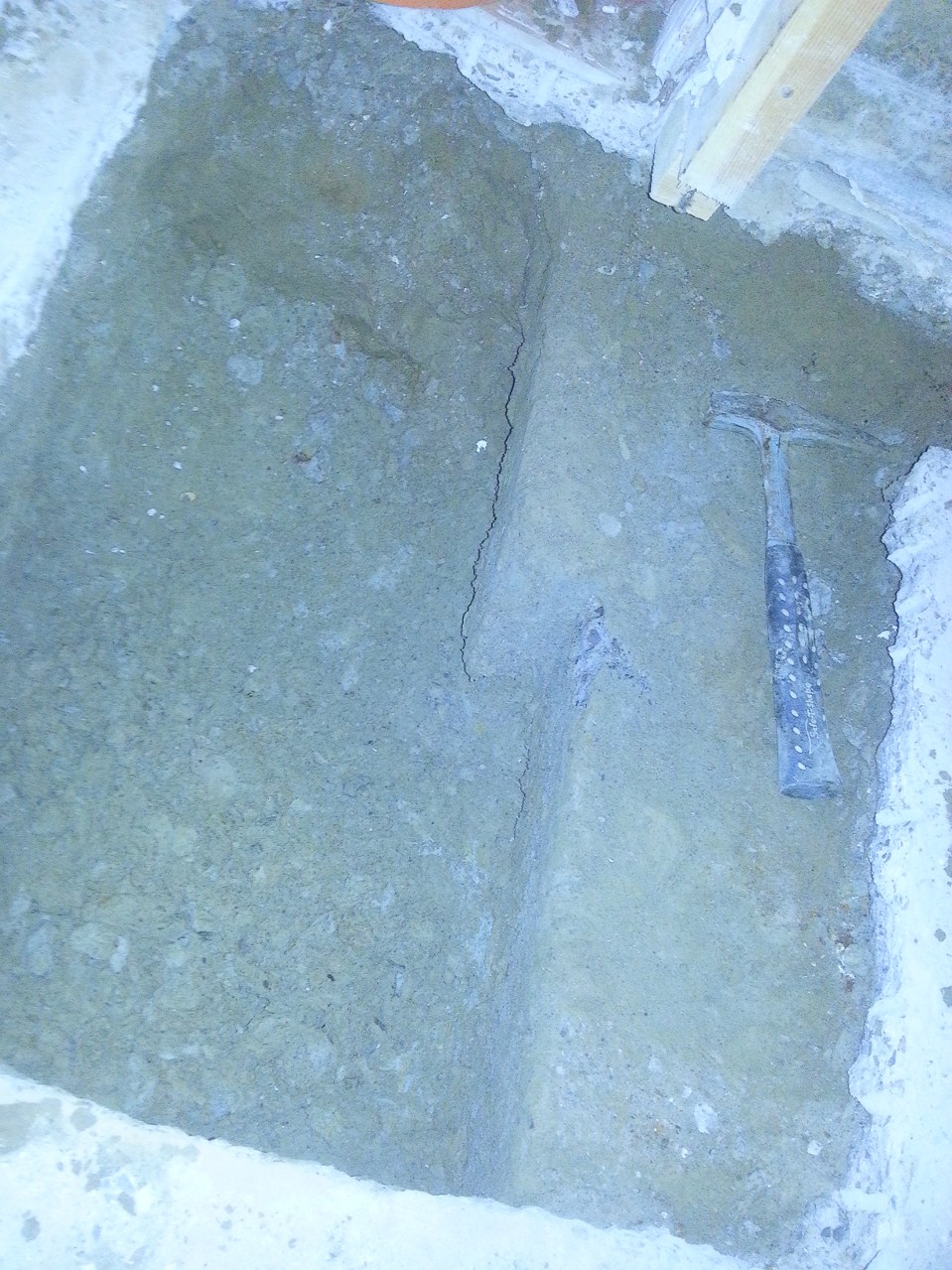
After 7 paragraphs of my regaling you with tales of my hole emptying experience, you probably can’t handle that many of my hole filling experience. So I will be brief. 11 bags of concrete were mixed 2 at a time, carried downstairs, and dumped into the hole. A piece of scrap rebar was used to jiggle and poke it so that it got into the corners. I smoothed off the top, and inserted my column base. And my footing was done:
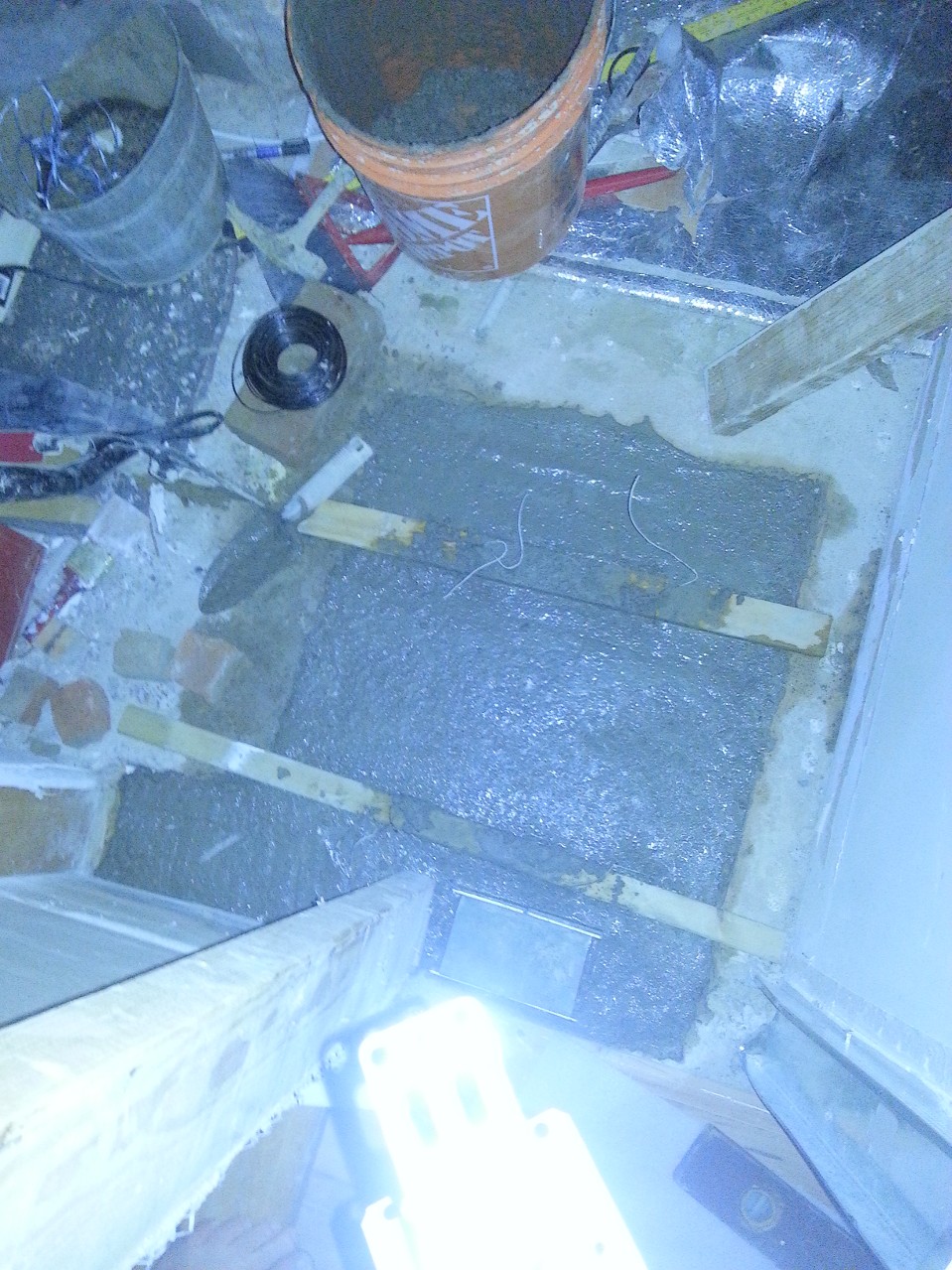
Finished footing
Next on the list: Attach the columns and smash plaster off the wall.
I’ll keep you posted.
Home Improvement Blog on Google+
Home Improvement Blog on FaceBook
Bloggers Wanted
Latest Articles
Topics
- Electrical (8)
- Introductions (7)
- Plumbing (3)
- Projects (13)
- Repair (4)
- Safety (5)
- Tips and Tricks (5)
- Tool Review (5)
- Tools (6)
- Uncategorized (5)